You can read a lot about programming. But you learn it mainly by doing yourself, making mistakes and solving those yourself. Searching for and solving errors yourself is called debugging.
Why is searching for and troubleshooting errors called debugging? A “bug” is a little, beetle or insect. Long ago computers consisted of electric switches. Between these switches, a beetle or fly could get stuck and blocking the switch. Because of the stuck switch, the computer no longer worked properly. To make the computer work properly again, the bug, beetle or fly had to be found and removed to make it work properly again. The syllable "de" in debugging means undo or remove. So debugging literally means removing an insect and comes from the first program error ever found.
![By Courtesy of the Naval Surface Warfare Center, Dahlgren, VA., 1988. [Public domain] via Wikimedia Commons](./Student%20guide/H96566k.jpg)
An example of a computer report from the Mark II computer. Here is the first bug found taped onto the computer report in 1947
So you're going to try a lot yourself, puzzle and learn from your own mistakes! You will do this with a robot, Landje Robot. Landje Robot is capable of the following things if you program it well;
To program you use a language. A language that your computer understands so you can explain what it should do. There are many languages, some languages are very suitable for writing games, others are better equipped to make complex calculations. If you start with programming there is a good chance that you do this in Scratch. With Scratch, you can make a program by sliding blocks together.
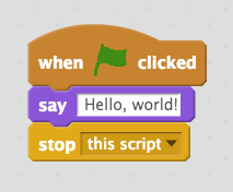
A simple example of a program in Scratch.
Hardly any programming language works like Scratch. Most programming languages require you to write a command to let the computer know what to do. Writing a program is more difficult than programming with Scratch. This is because a computer is very precise and very stupid (really!). A computer only understands you if you tell it exactly what you want.
// This is understood by the computer
Serial.println("Hi") ;

// This the computer does not understand
Serial.Println("Hi") ;
Do you see the difference between the two instructions ?
Programming Landje Robot will be done in the programming language C (see). As you could see in the previous example, English words are used here.
In this lesson you will write the first program. Programs can be written in many ways, but usually you do this with a program that helps you with writing programs. Such a program is called an Integrated Development Environment. A mouthful, that's why everyone is talking about an IDE. The IDE you are going to use is ‘ in the cloud ’. You must have heard this term before. It means nothing but that you can use the program anywhere in the world if you only have an internet connection and a computer.
You will use the IDE Arduino Create.
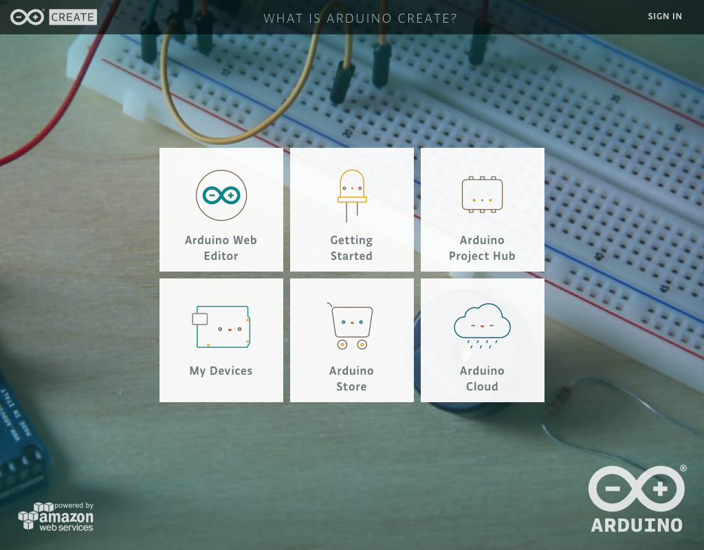
To start the IDE click on the button Arduino Web Editor. In the IDE you can click on various tabs on the left. Click on Sketchbook. A program in this IDE is called a sketch. To the right of the Sketchbook you will see sketches that you have saved in the book.
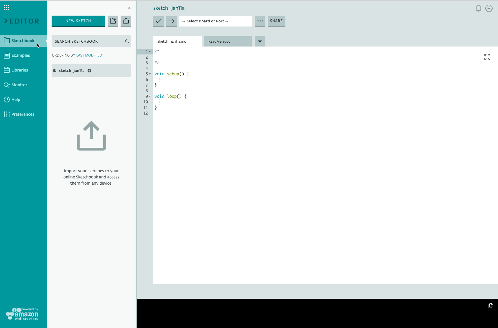
Now create a new sketch by clicking NEW SKETCH. A new sketch automatically gets a name like ‘sketch_jan11b’. This is often not useful, it would be clearer if the sketch is called my first sketch.

When you create a new program, it looks like this.
/*

*/

void setup() {

}

void loop() {

}At the beginning of the program is a /* and a */. If the computer runs a program then nothing will be done with what is between /* and */, the computer ignores it. You can use this to describe what you do in the program. This way you can add comments or remarks to the program. You can also use it to 'disable' a part of a program. For example;
/*
Here I explain what the program will do.
The program will show a text.
*/

Serial.println("I show this text") ;

/*
Serial.println("This instruction is ignored");
*/
If you just want to add one line comment or ignore one instruction for a moment, you can also start the line with //. So you often use /* and */ if you want to ignore multiple lines and // for one line.
/*
 Everything between /* and */ is ignored.
*/

// But this line also
setup() and loop() are functions. A function is a group of instructions that belong together. The instructions that belong together are between { and } after the name of the instruction. By calling the function in a program instead of an instruction, you can execute multiple instructions in one time. The function setup() is automatically called one time when you start the program. Loop() is a function that is executed over and over again.
Now type the following instructions in the function setup().
Serial.begin(9600);
delay(5000);
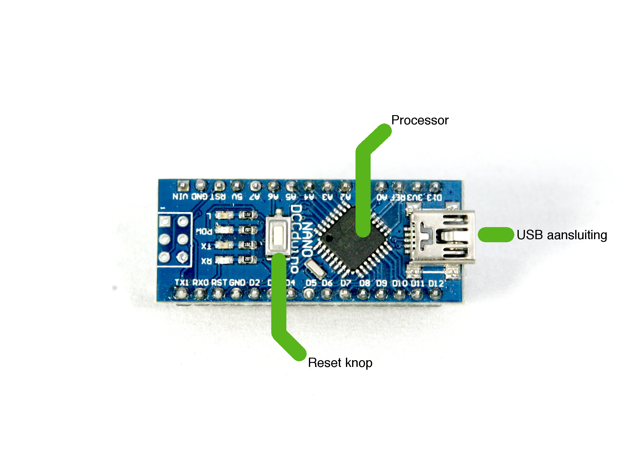
Serial.println("Hi!");You have now written your first program! But how do you run this program? In order to use a program you need a computer. Because you can't put a whole laptop on a robot we are going to use a very small computer. This computer is called an Arduino Nano. Nano means very small and comes from the Latin word Nanos which means 'dwarf'. Like every computer, the Nano has a processor or CPU, this is the brain of the computer with which it will run your program. There is also a small reset button on it, with which you can restart the Nano if necessary. Because the Nano is so small, you cannot connect a keyboard or monitor to it. You use your computer as a monitor and to send programs to the Nano.
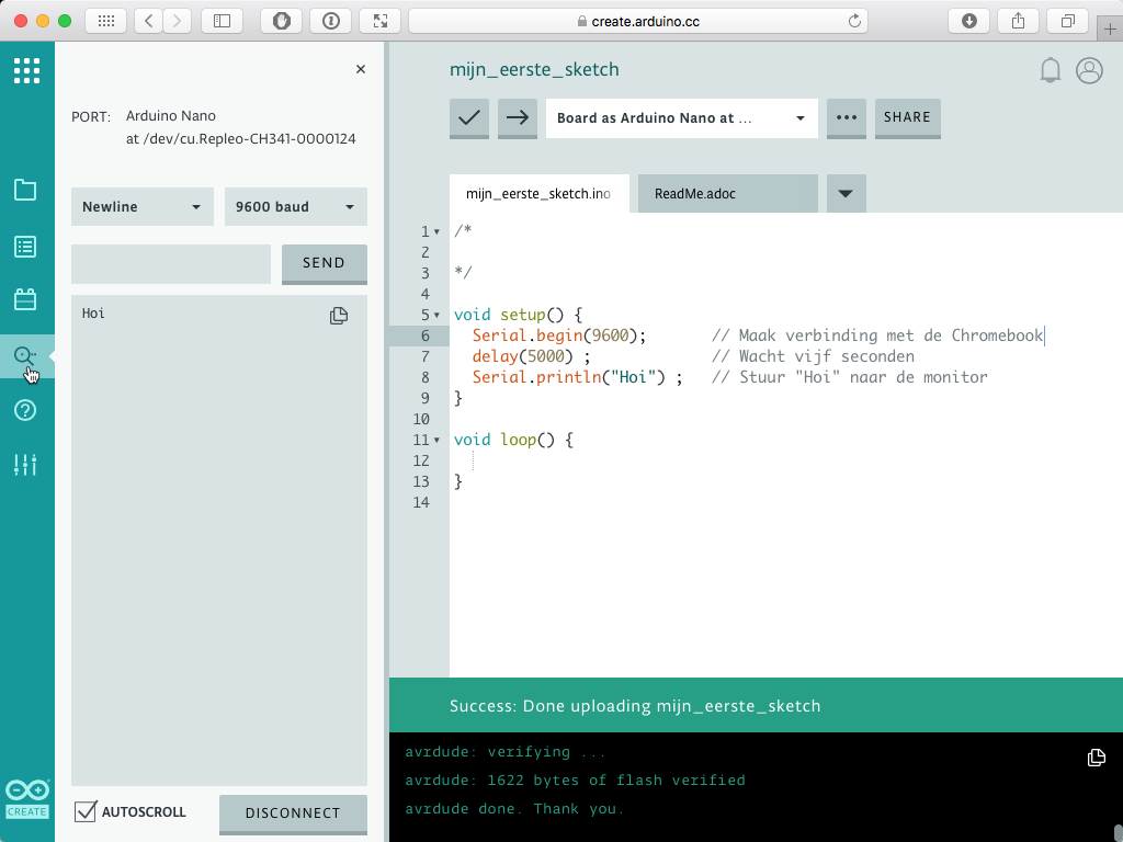
Now it's time to start your program. Open your Arduino Create page again and now first left click Monitor. To the right of the editor a window will appear. In this window we can show text that the Nano sends to the Chromebook. This is the screen of your Arduino. Now start your first program on the Nano. Do this by 'uploading' the program, sending the program to the Nano. Uploading is done by clicking on the arrow that is shown above the program. Wait a few seconds and if you have done everything right a text will appear in the Nano Monitor.
The setup() function is only called once when the Nano is started. The function loop() is called repeatedly till you turn the Arduino off. You will see this if you also send something to the monitor in the function loop. For this we use a part of the same instructions as we used in setup(). The instruction Serial.begin(9600) may only be used in setup(). This instruction ensures that the Arduino connects to the Chromebook. With the instruction delay() you let the program wait a while. Between the round brackets you have to specify how long you want to wait. You have to specify this in milliseconds, thousandths of a second, so if you specify delay(1000) the Nano 1000 * 1⁄1000s waits. This is exactly 1 second. With Serial.println() you print a text to the Monitor in Create. What you want to print must always be in double quotes, so ' " '.
Did you succeed ? Lovely!
As you may have seen, after every instructe there is a ' ; '. This is for the computer the same as a space that we place between the words in written text. That makes it a piece of readable dontyouagree? So you may place multiple instructions on one line. So for a computer, the left and right examples are evenly as easy to read. To keep a program readable for you and the Nano as well, we agree to start every instruction on a new line and end with a ' ; '
Serial.begin(9600);
delay(5000);
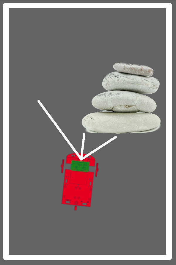
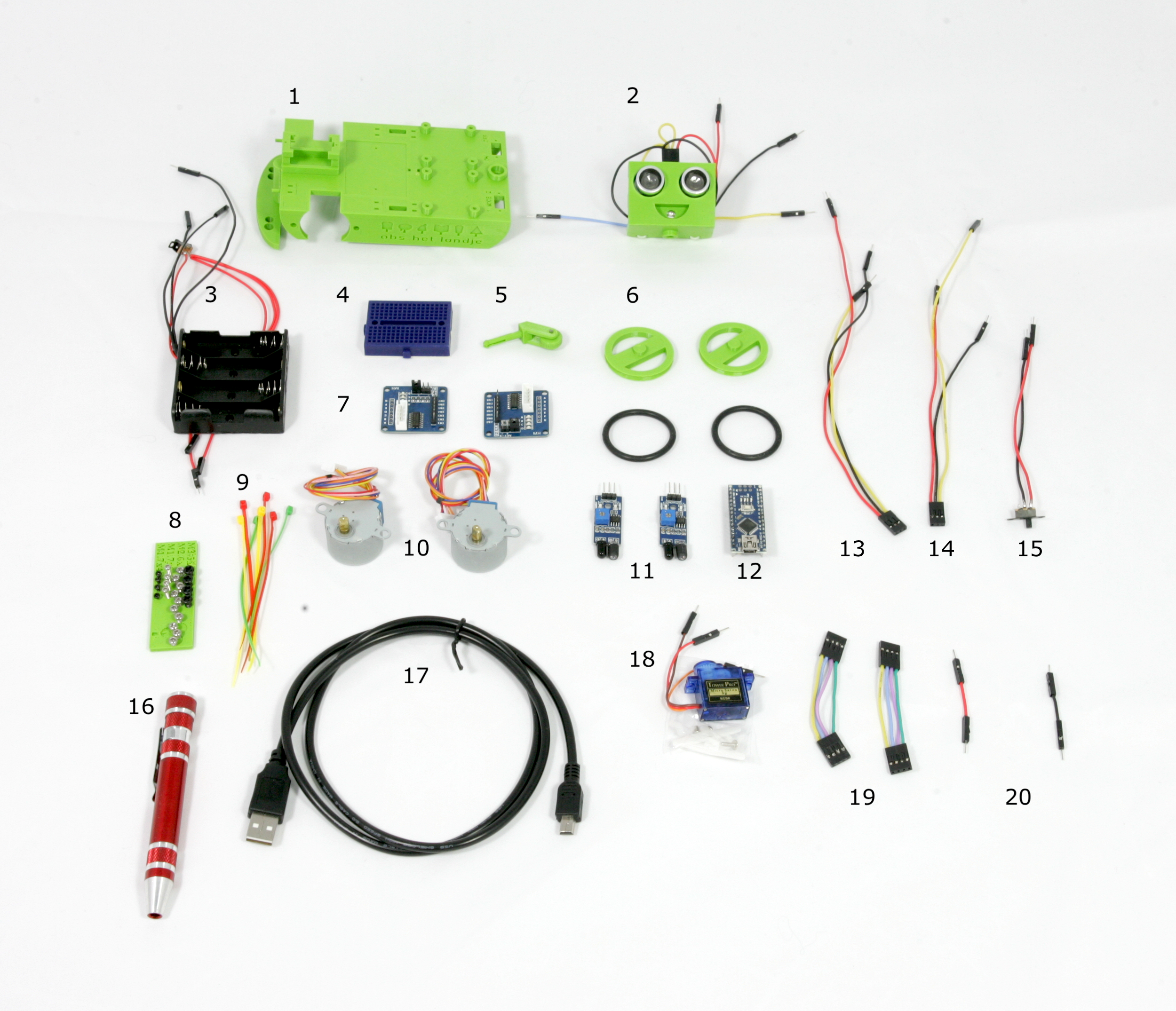
Serial.println("Hi");Serial.begin(9600);delay(5000);Serial.println("Hoi");The robot consists of several parts. With these parts you will assemble the first part of the robot. Below you see an image with all parts with a number. Below the picture you see a list with numbers and the name of the part and a short explanation of what this part is for.
| Number | Name | Descriptiom |
|---|---|---|
| 1 | Robot frame | This is the frame of the robot, on which all parts will be attached. |
| 2 | Robot head | The robot can 'look' with his head. The robot looks by making a sound that is inaudible to us. By measuring how long it takes for the echo of the sound to return, the robot can calculate a distance to an object in front of him. This high sound is called ultrasonic sound. Bats and dolphins also use this sound for better viewing. |
| 3 | Battery holder | The battery holder has space for 4 AA batteries of 1.5 volts. Because the batteries are connected in series, the battery holder gives about 6 volts. |
| 4 | Breadboard | A Breadboard is a plastic expirment board in which electronic components can be placed. In the board are per row of holes metal strips that connect those rows of holes. By means of the wires and the breadboard all the electronic parts of the robot are connected to each other. |
| 5 | Swivel castor | This is the rear wheel of the robot. It can turn around so that the robot can make good turns. |
| 6 | Front wheels | The robot has two front wheels with rubber tyres. These two wheels can rotate independently of each other |
| 7 | Darlington drivers | These chips ensure that the Arduino computer can control the motors. Computers can often only send small signals in the form of small currents. A motor needs a lot of power and can't work directly on the small signals from the computer. The Darlington drivers translate the small signals into stronger signals. So it is a kind of amplifier for a computer. |
| 8 | Screw set | Some parts need to be fixed with screws. There are different types of screws. The size of a screw always starts with M. The M stands for the Metric system. In the metric system we express distances, weight and temperature in milli-meters, kilograms and degrees celcius. There are also other sysyems like Imperial that is used in Great Britain or some American countries. They use inches, pounds and degrees Fahrenheit to express distances, weight and temperature. After the M comes a number that indicates the diameter of the screw in millimeters. After the first number comes an 'X' followed by another number. This last number indicates the length of the screw in millimeters. A screw of M3.5x6 has a diameter of 3.5mm and is 6 mm long. In the screw set are M3.5x6, M2.6x4, M1.7x8 and M1.5x4 screws. |
| 9 | Cable Ties | Cable ties or ty-raps are plastic strips with which you can easily tie wires together. |
| 10 | Stepper motors | Stepper motors are like the name says motors that can make steps. These motors have to make 64 steps to turn around its axis once. The motor also contains a number of cogs that slow down the motor. Because of this delay the motor eventually has to make 4096 steps to rotate the shaft on the outside one time. This allows the robot to cover a specified distance very precisely. |
| 11 | Reflection sensors | These two meters measure whether an infrared light that is invisible to us is reflected. These sensors can later be used to measure whether the robot is moving over a dark or light-coloured line. |
| 12 | Arduino Nano | An Arduino Nano is a mini-computer. The computer makes sure that the robot does what you have programmed. The Arduino makes sure that the motors are moved and data from the sensors are read. |
| 13 | Reflection sensor cable right | This cable connects the right reflection sensor to the Arduino |
| 14 | Reflection sensor cable left | This cable connects the left reflection sensor to the Arduino |
| 15 | Selector switch | With the selector switch you can determine what the robot will do. |
| 16 | Screwdriver | The tool you need to assemble the robot. |
| 17 | USB cable | This will connect the robot to your Chromebook so you can program it. |
| 18 | Servo motor | A servo motor is a motor whose shaft can be turned to a position. The motor can't rotate multiple turns, but only a little to the left and a little to the right. This motor allows the robot to look to the left and right. |
| 19 | Darlingon drivers cables | These cables will connect the Darlington drivers to the Arduino. |
| 20 | Connection wires | These short wires will connect the + and - of the batteries with a row on the breadboard so that several motors and sensors can be connected to the battery. |
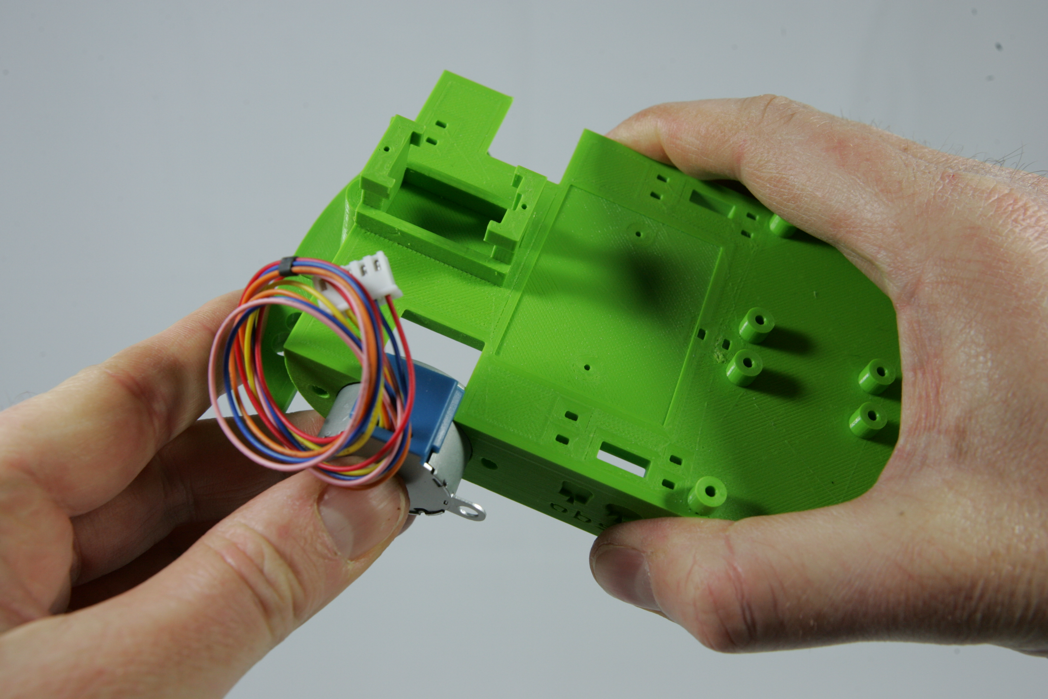
The first step is to mount the stepping motors on the frame. Slide the motors one by one into the frame as shown in the pictures below. Make sure that the blue cap of the motor sticks out above the frame. Then screw the motors in place with 4 M3.5x6 screws.
Tip: Als je iets op de fotos duidelijker wilt zien, klik dan op de foto zodat hij automatisch wordt uitvergroot.
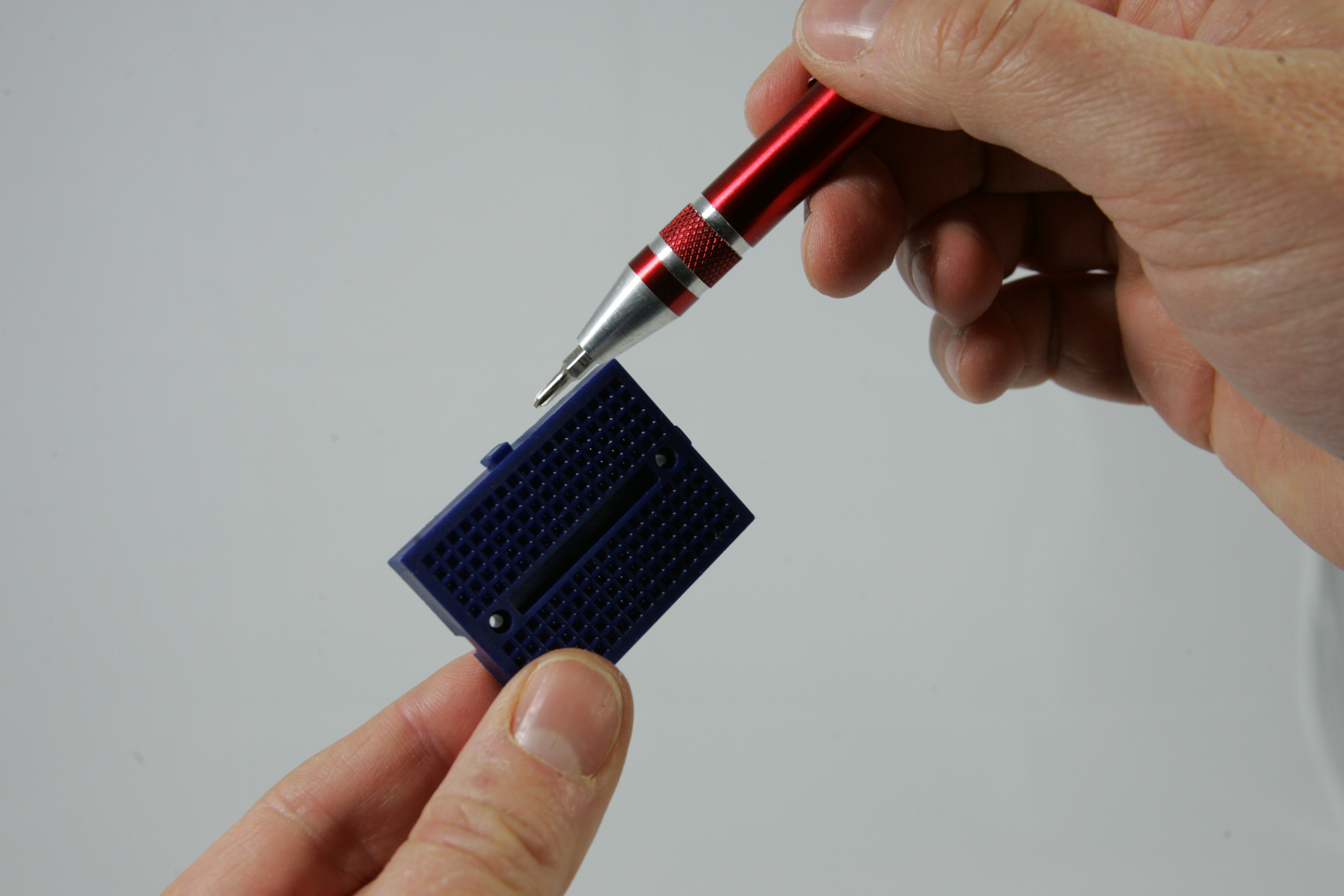
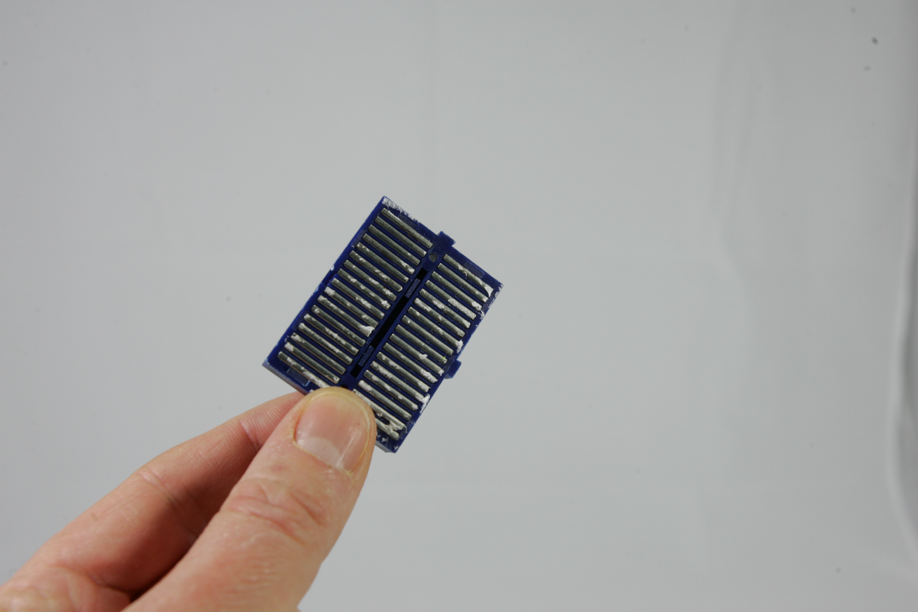
Now you are going to screw the breadboard on the frame. Attention! The breadboard has a ridge on one of the long sides. This should point to the front of the robot when screwing it in place. Take a look at the breadboard from the back. Do you see how the holes are connected with each other by the metal strips?
Now screw the breadboard on with two M1.7X8 screws. Did you pay attention to which side the cam points to the breadboard?
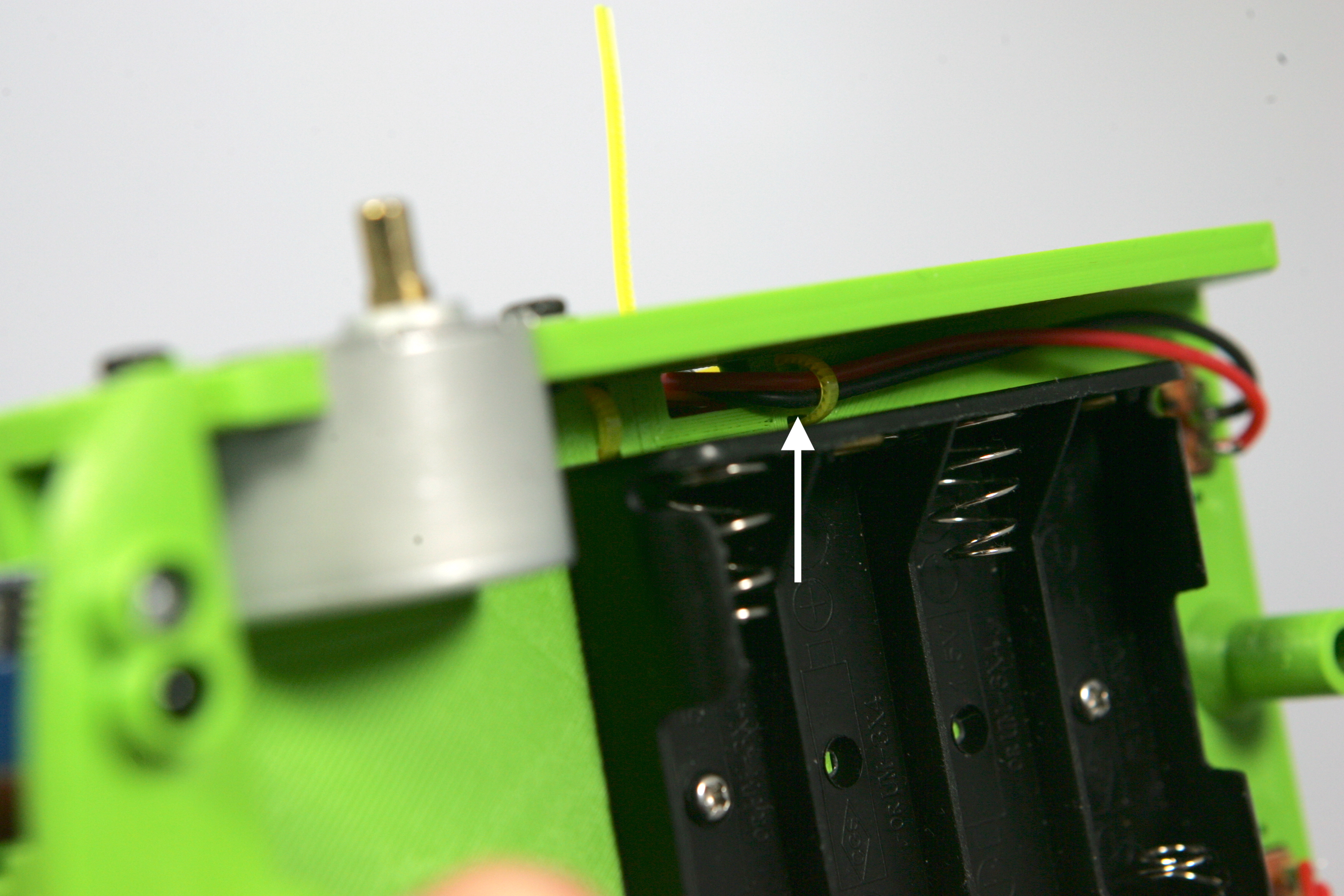
Now turn the frame upside-down and screw the battery holder on with two M2.6x4 screws. Make sure that the wires of the battery holder are in the left center of the frame.
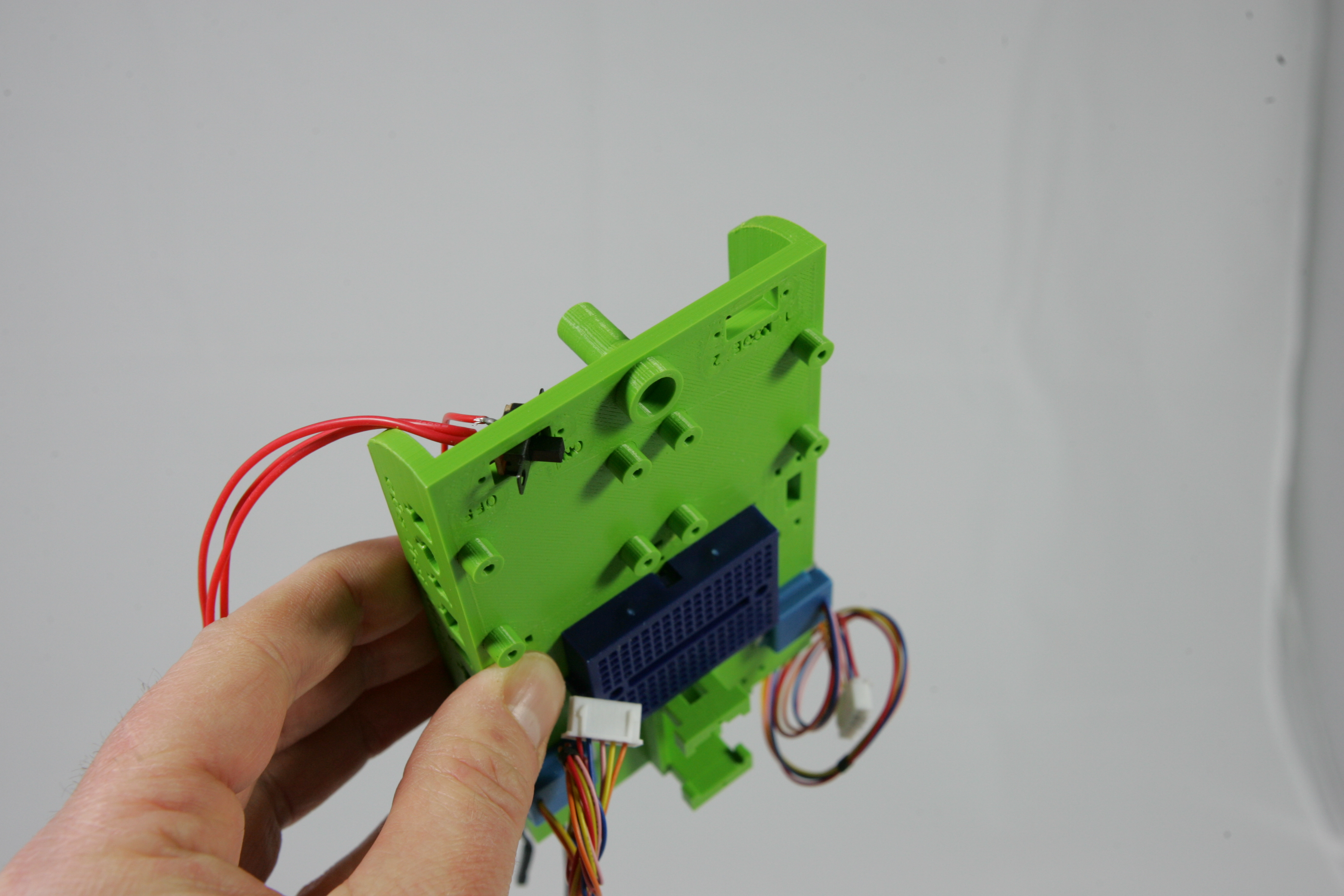
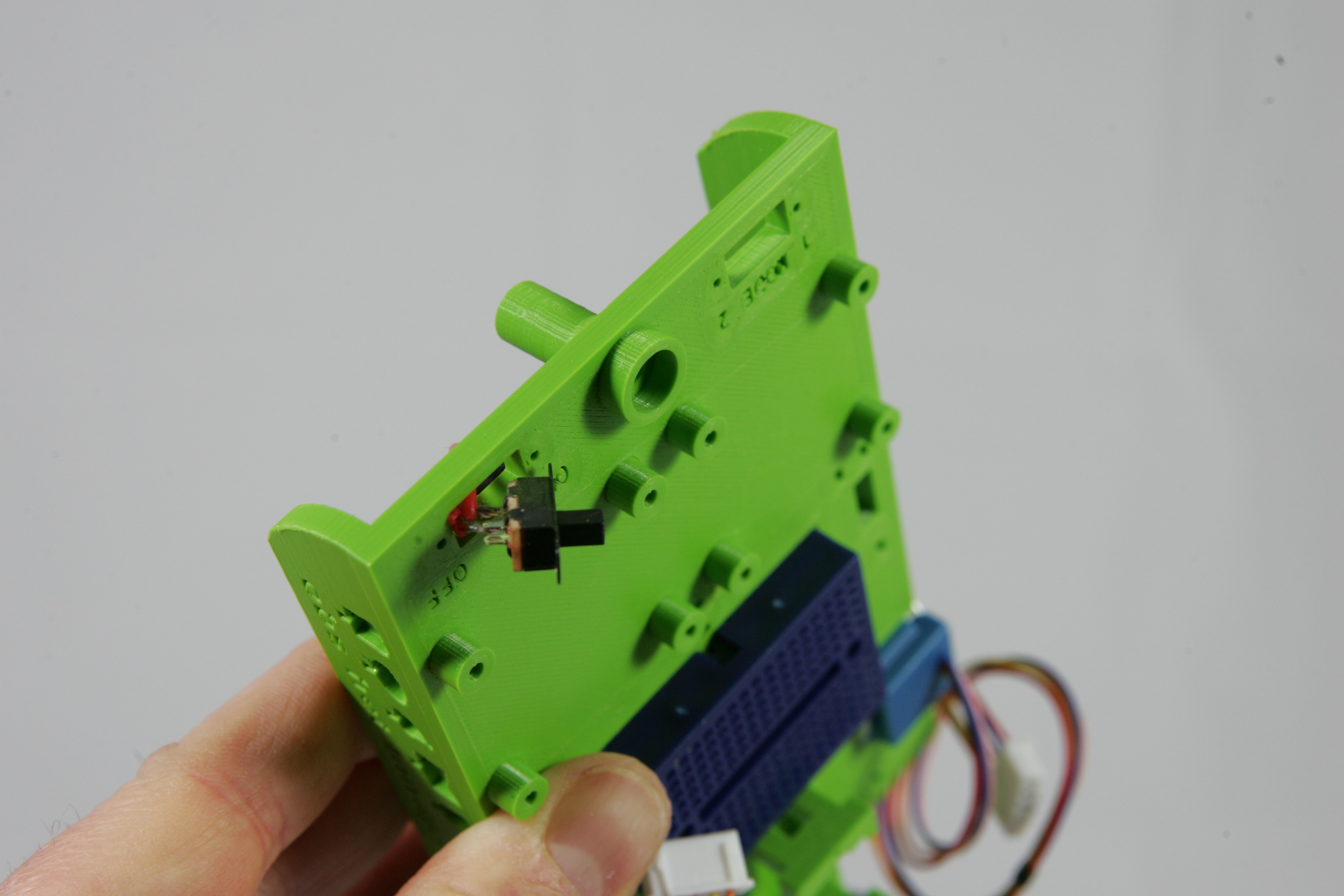
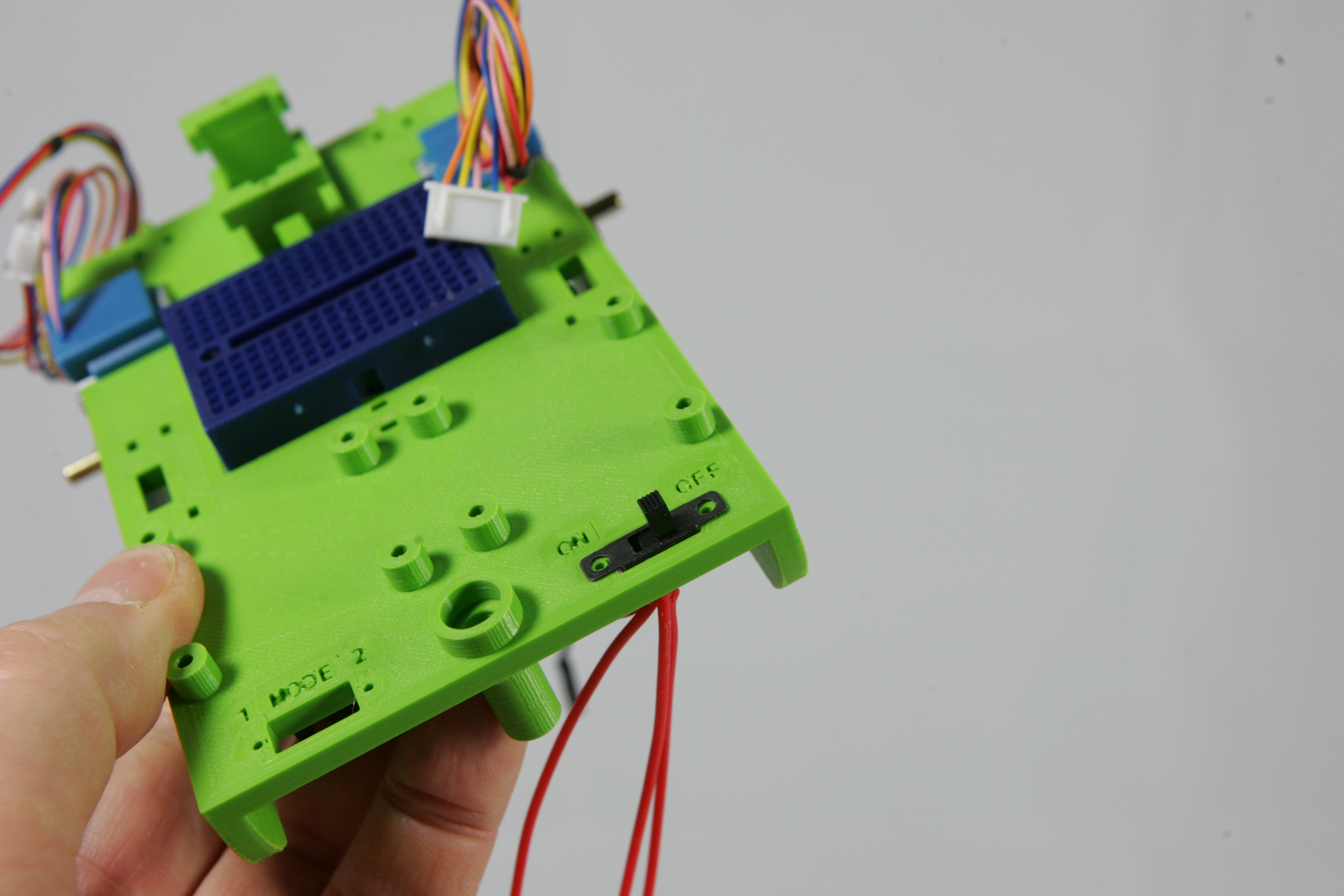
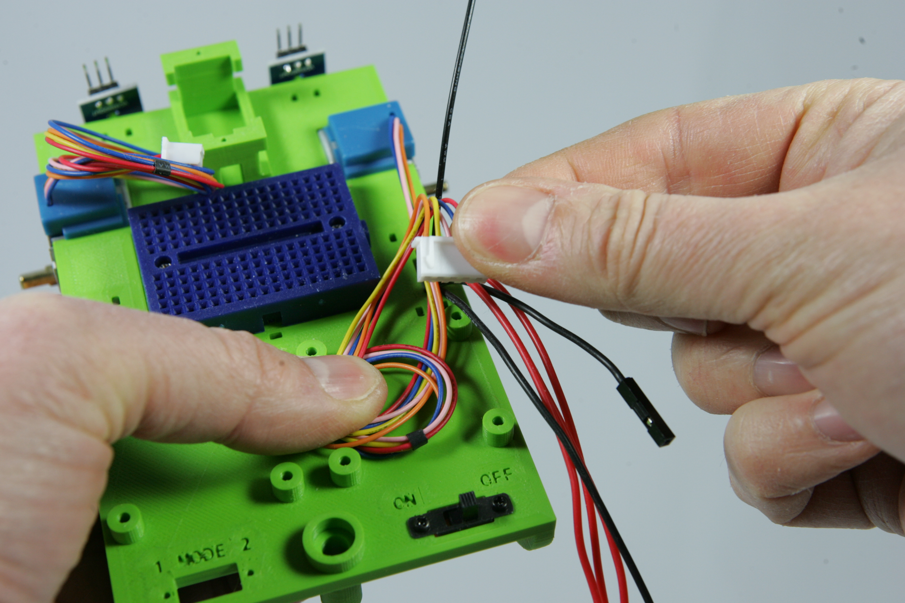
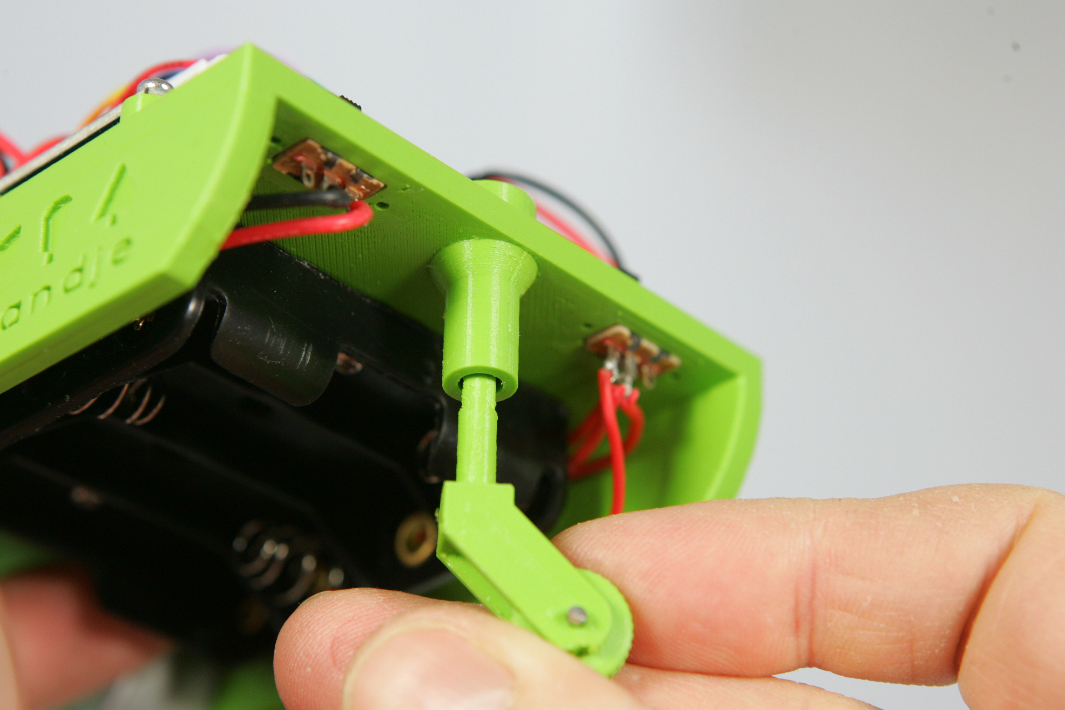
There is a small switch connected to the battery holder. Push it carefully through the opening marked "ON OFF". Look carefully at the pictures for the position of the switch when you push it through the opening. The cam of the switch must first pass through the opening. It's a bit of a fiddly job, but with some patience you should succeed. Does a wire break? Don't worry, we can solder it back on.
Now push the switch from the top into place. The switch must have been turned correctly. If you look at the bottom of the switch you see three connections. On two of these three connections a wire is soldered. The connection without wire should be on the side of the text "OFF ". Now feed the other wires through the hole.
Tighten the switch with two M1.7x4 screws.
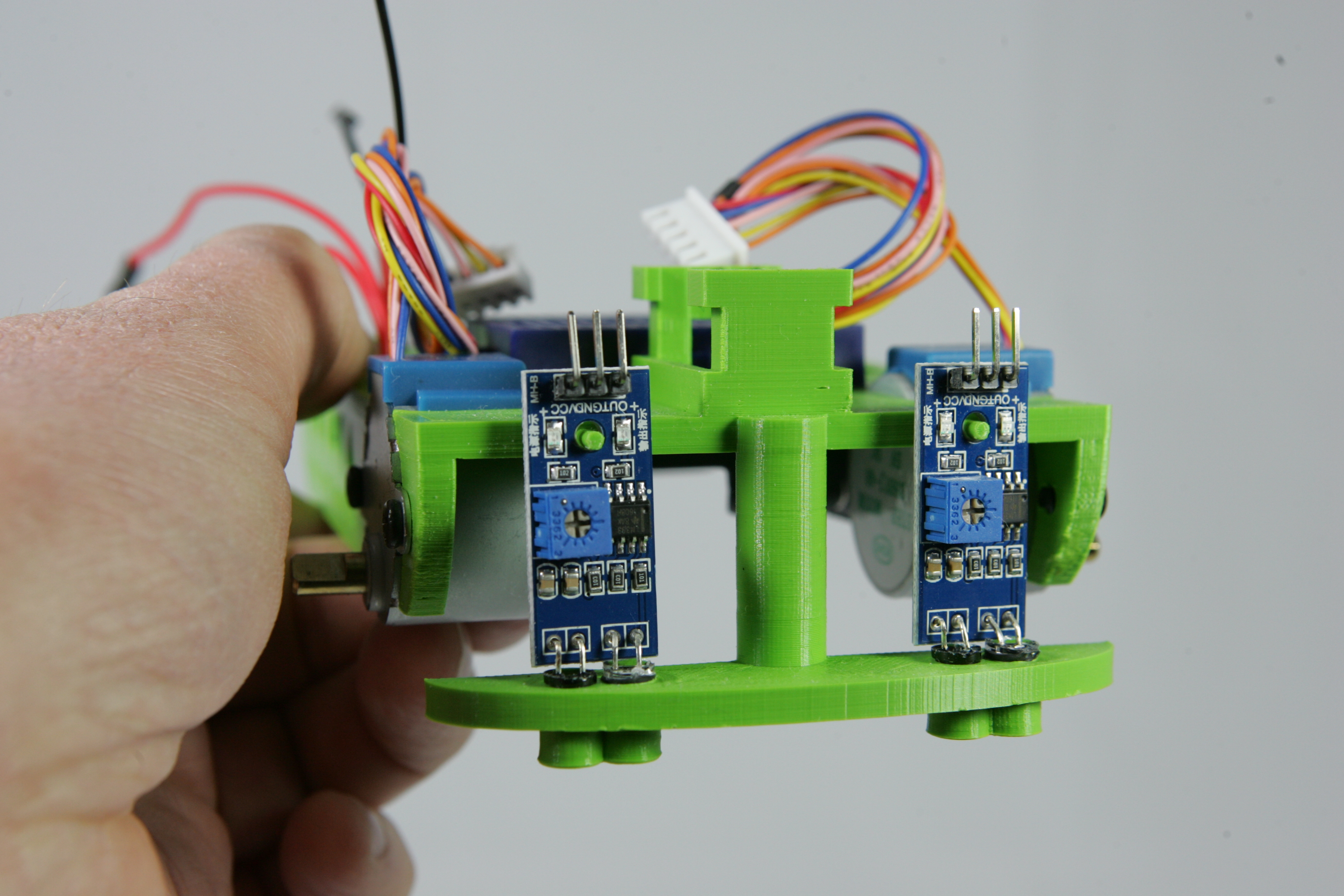
On the front of the frame, press the reflection sensors one by one with the LEDs carefully into the two holes. Make sure you place the sensor in the right direction. The component side of the circuit board, the side on which the parts are soldered, must face forward. Both holes do not have the same size. The bright LED with the rubber ring should be in the largest hole. If the LEDs are pushed far enough through, then the small rod should stick through the hole of the circuit board.
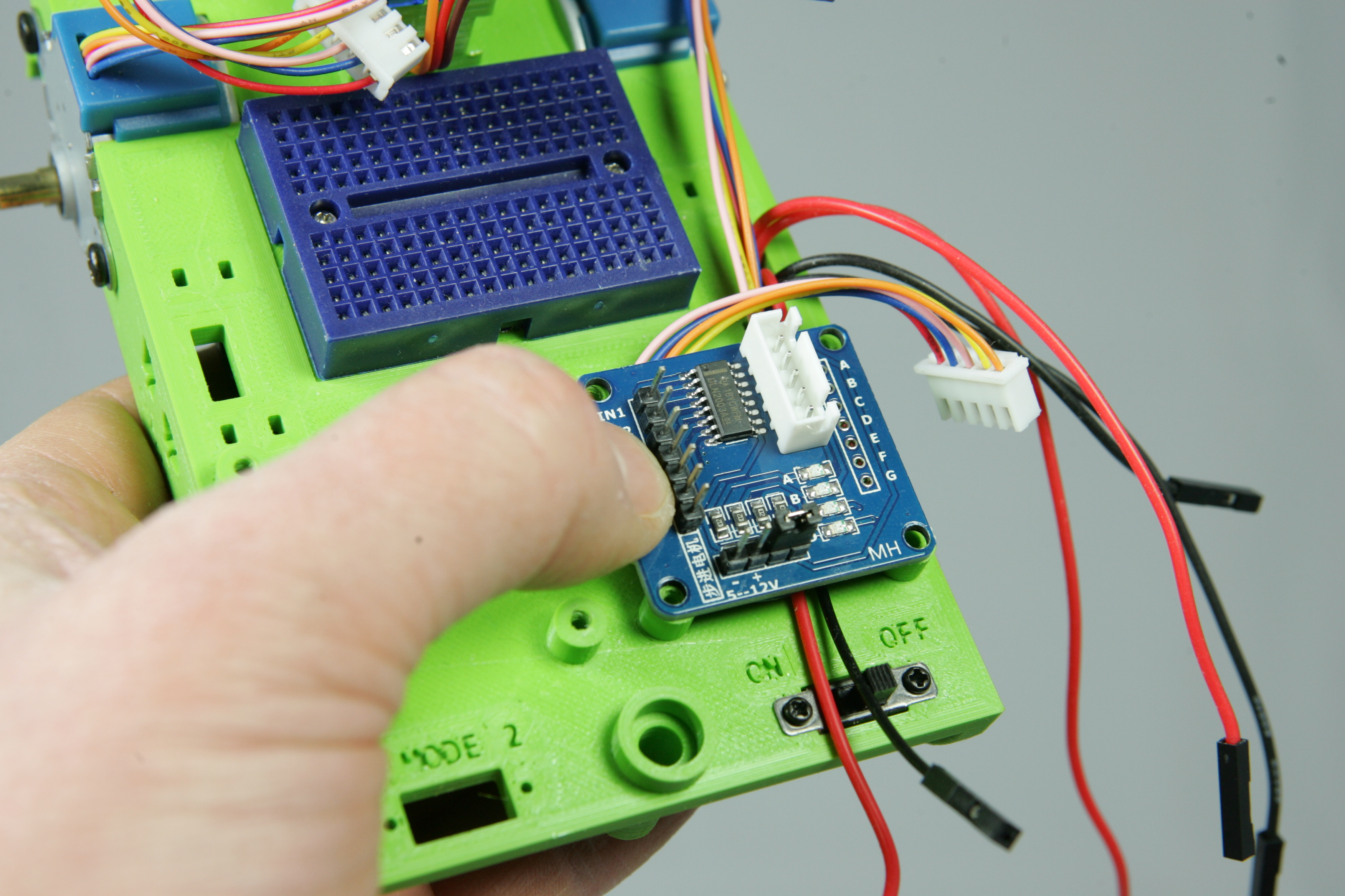
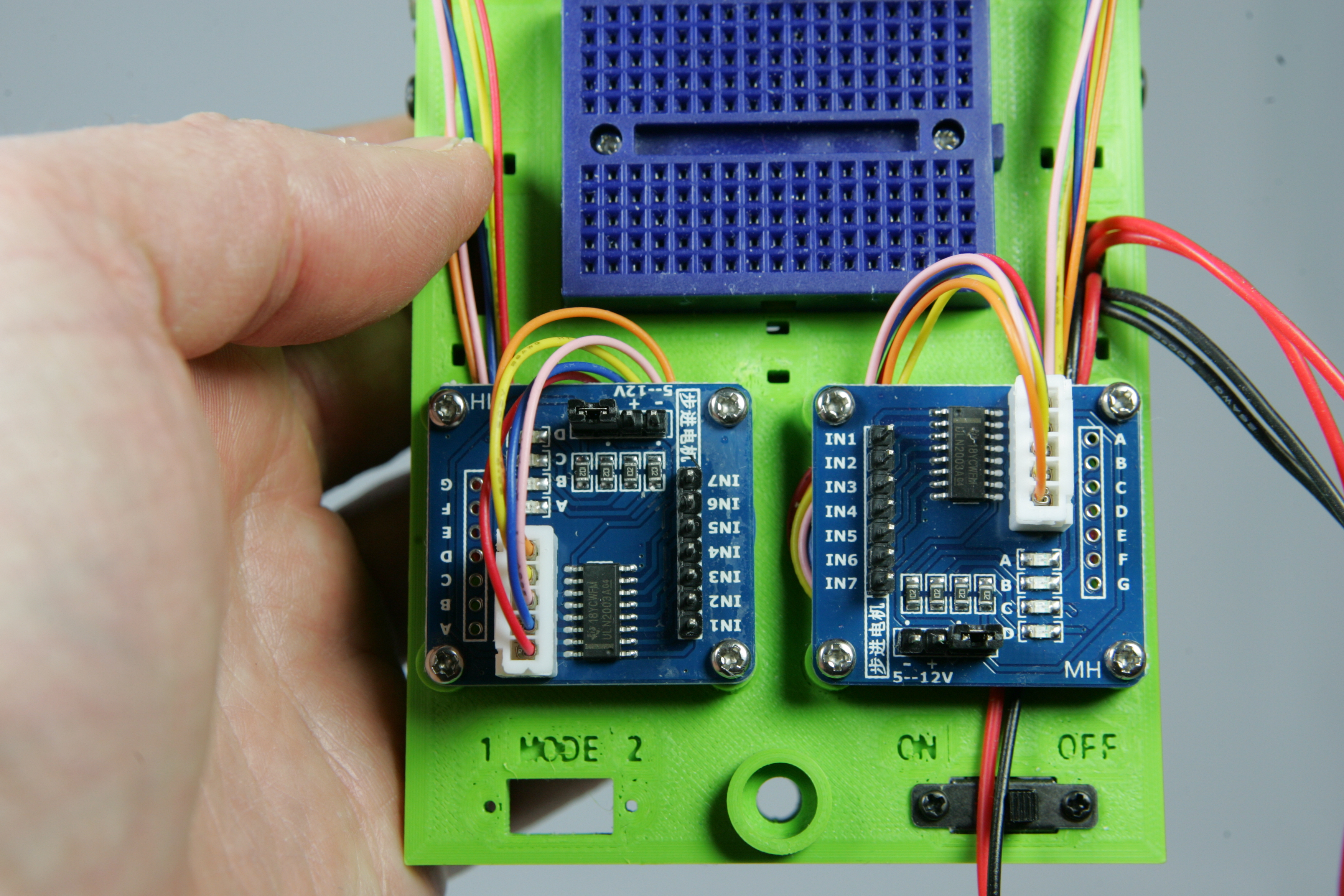
Now that the sensors are in place we are going to fix the Darlington drivers. Roll up the wire of the right stepper motor a bit between the four screw holes. Make sure that the connector at the front can protrude a few centimeters as shown in the first picture.
The Darlington driver still needs electricity to run the motor. In an earlier step you pulled the wires of the battery holder through the hole on the right side of the frame. These are three black (negative) wires and three red (positive) wires. The wires have both male connectors, the connectors with a pin, and female connectors. Now take the longest black and red wire with a female plug. Place these wires under the stepper motor wire in the direction of the switch. Keep a finger on the wires so they stay in place.
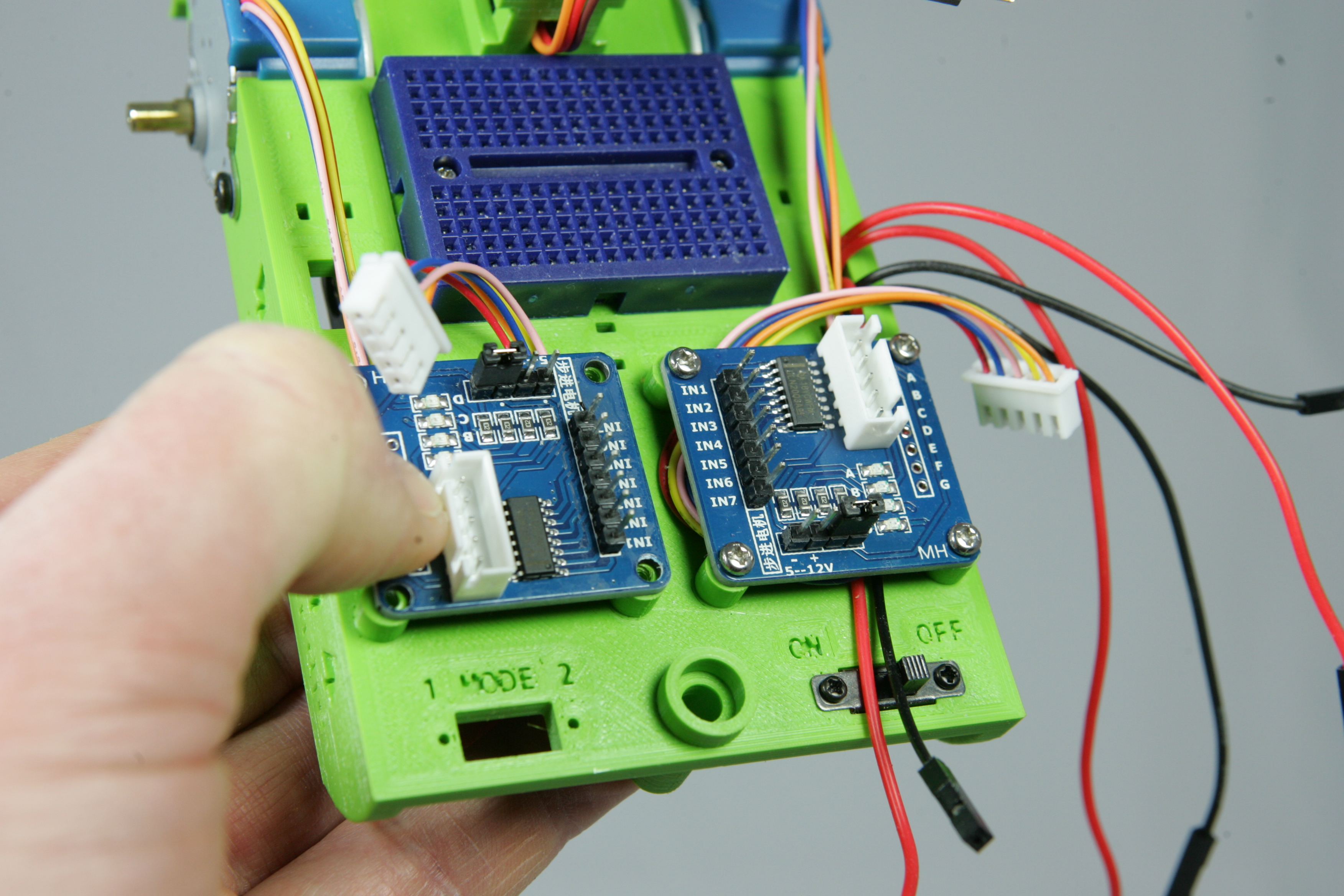
Now place one of the Darlington drivers over the wires so that the holes are exactly over the screw holes. Pay attention how you place the driver, the white connector should point to the outside. Then screw the driver with four M2.6X4 screws.
Now place the other Darlington driver in the same way as the first one. Only with this driver the wires of the battery don't have to be placed yet.
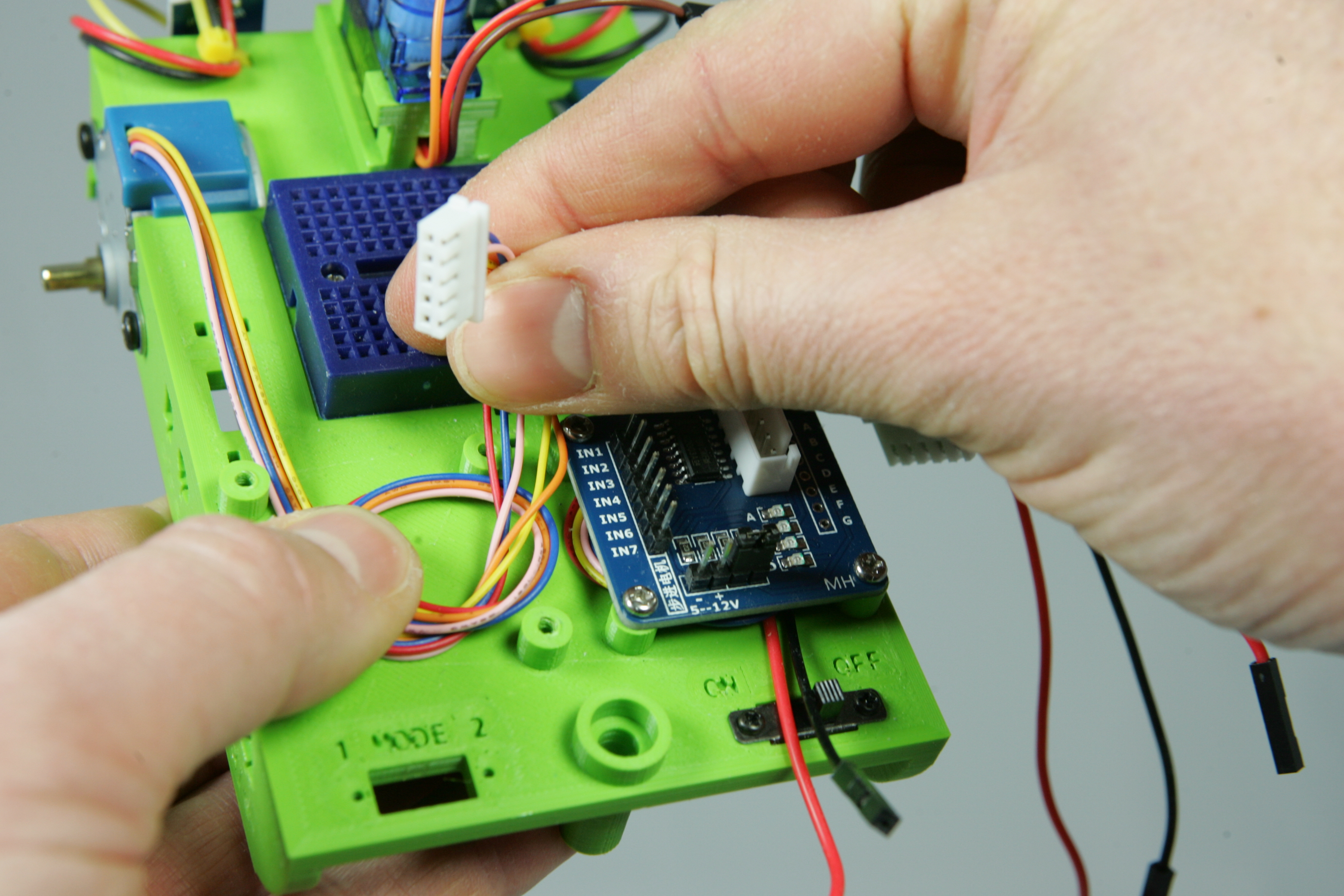
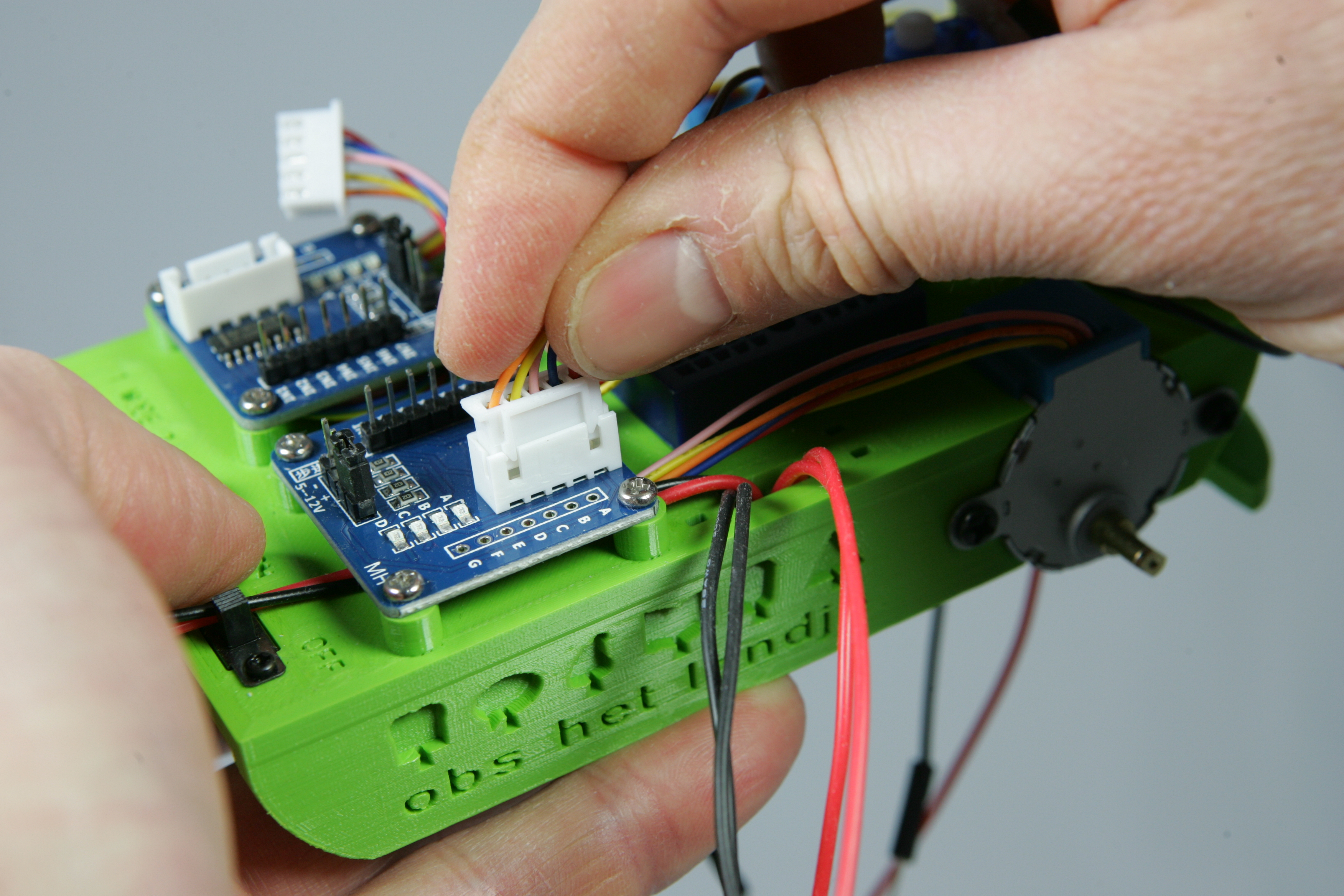
Now carefully press one by one the white connectors on the connector of the Darlington driver. Look carefully how you place the connector, they can only be placed on it in one way.
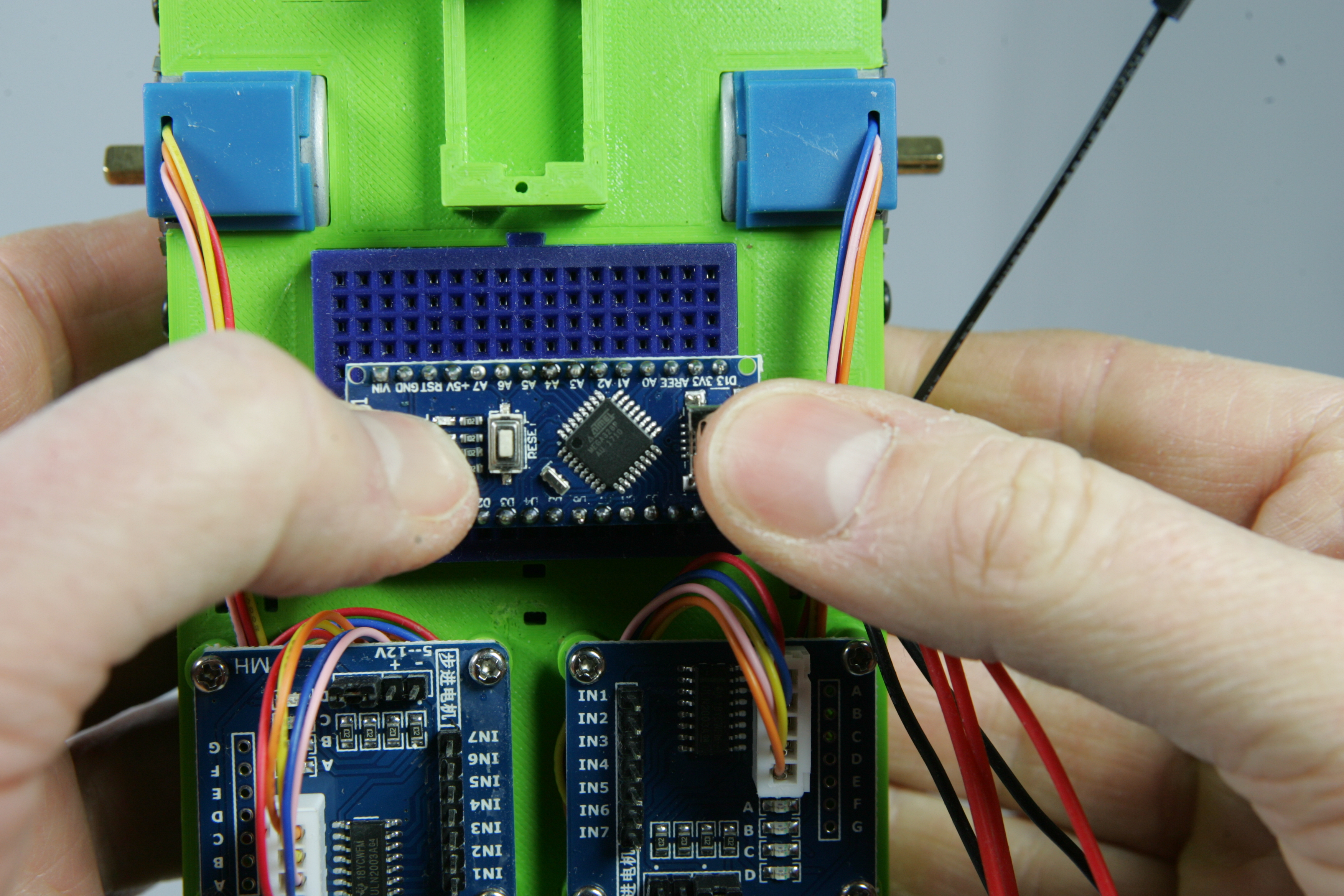
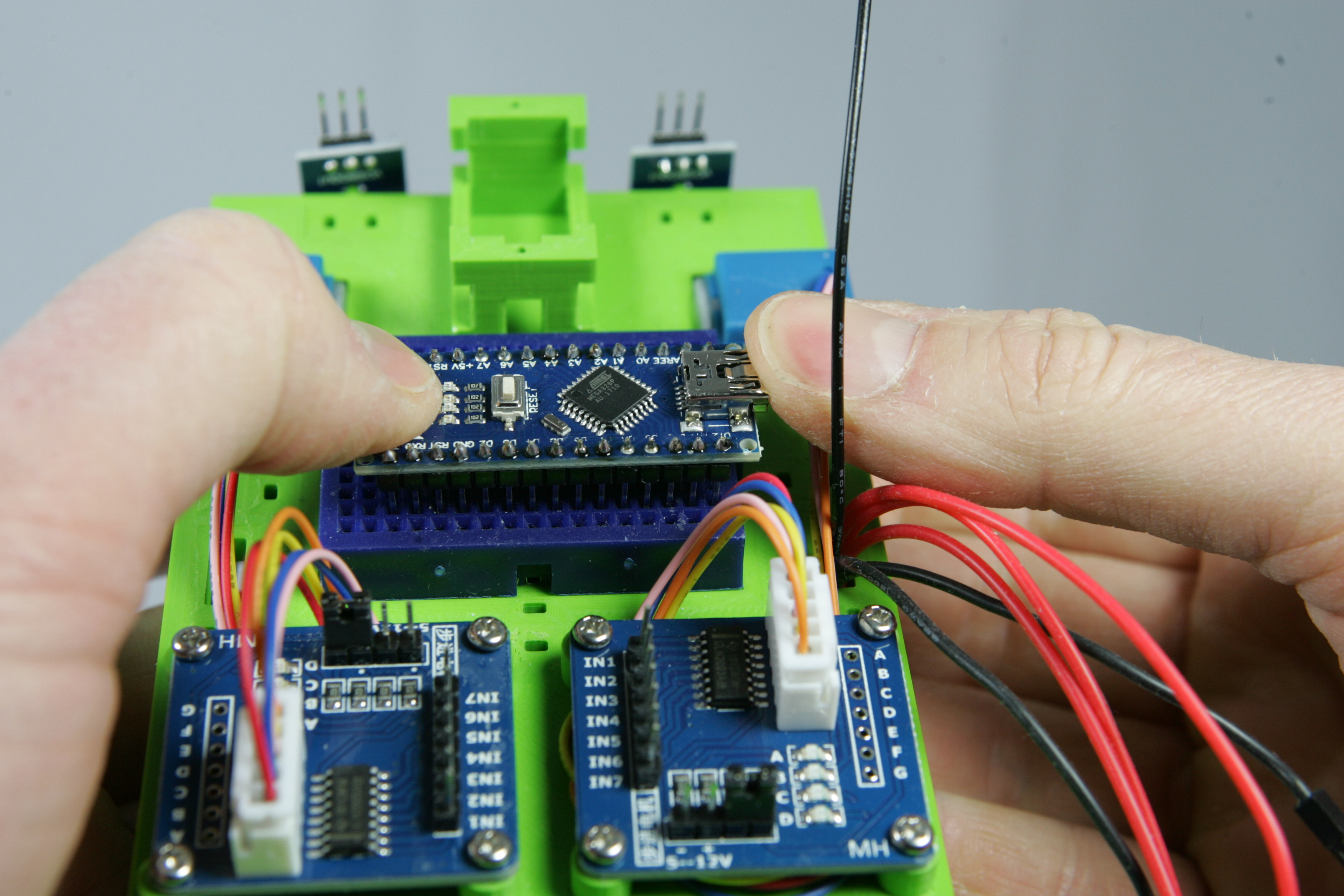
Put the Arduino on top of the breadboard. Do not push it in the breadboard yet. Put the pins so that they;
Is the Arduino placed right ?! Press it very carefully with two thumbs in the breadboard. Don't use too much force and make sure all legs are pressed into the breadboard and are not bent accidentally.
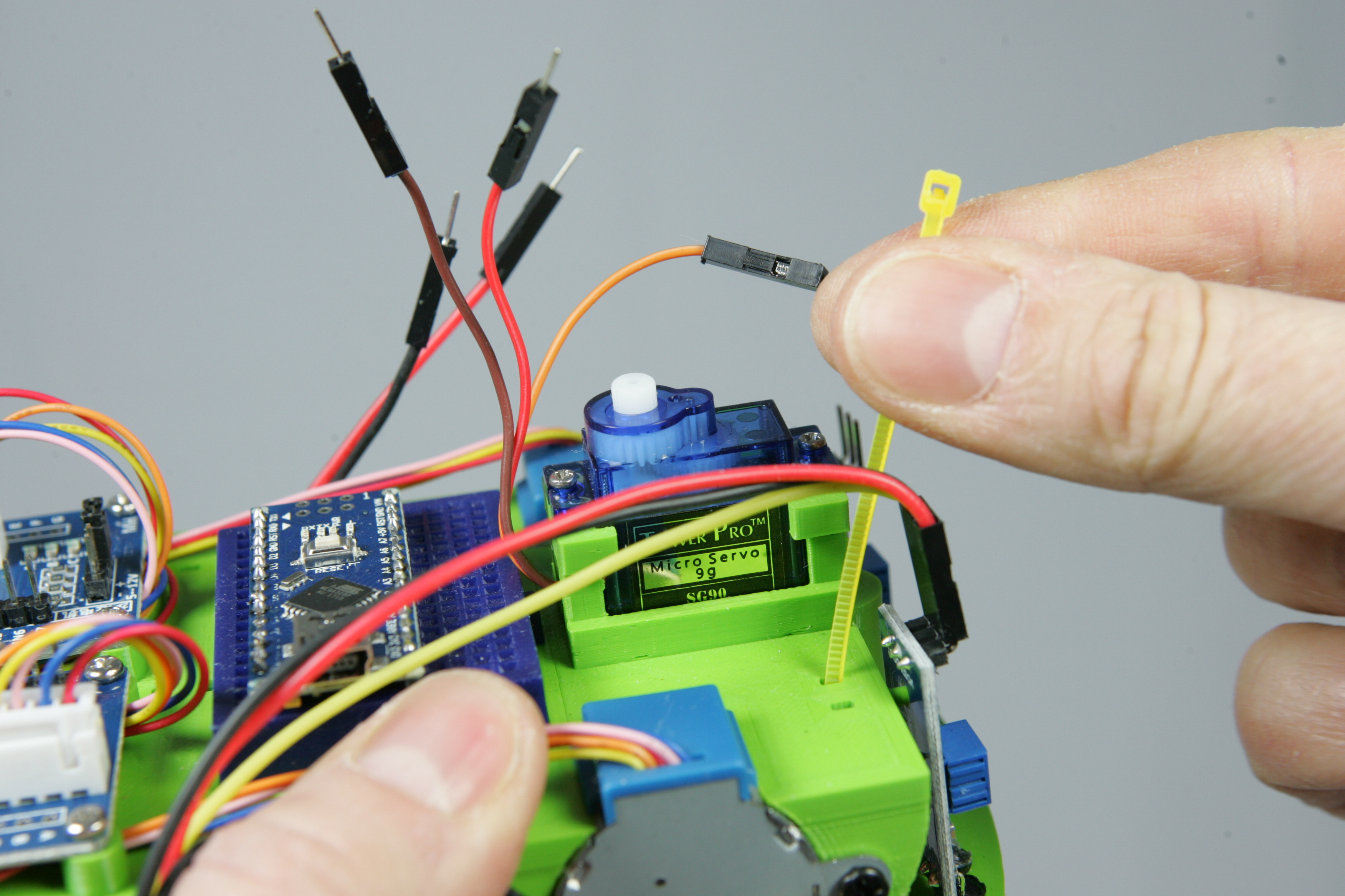
Feed the three wires of the servo through the hole and push the servo into place.
Tighten the servo motor with two M1.7x8 screws.
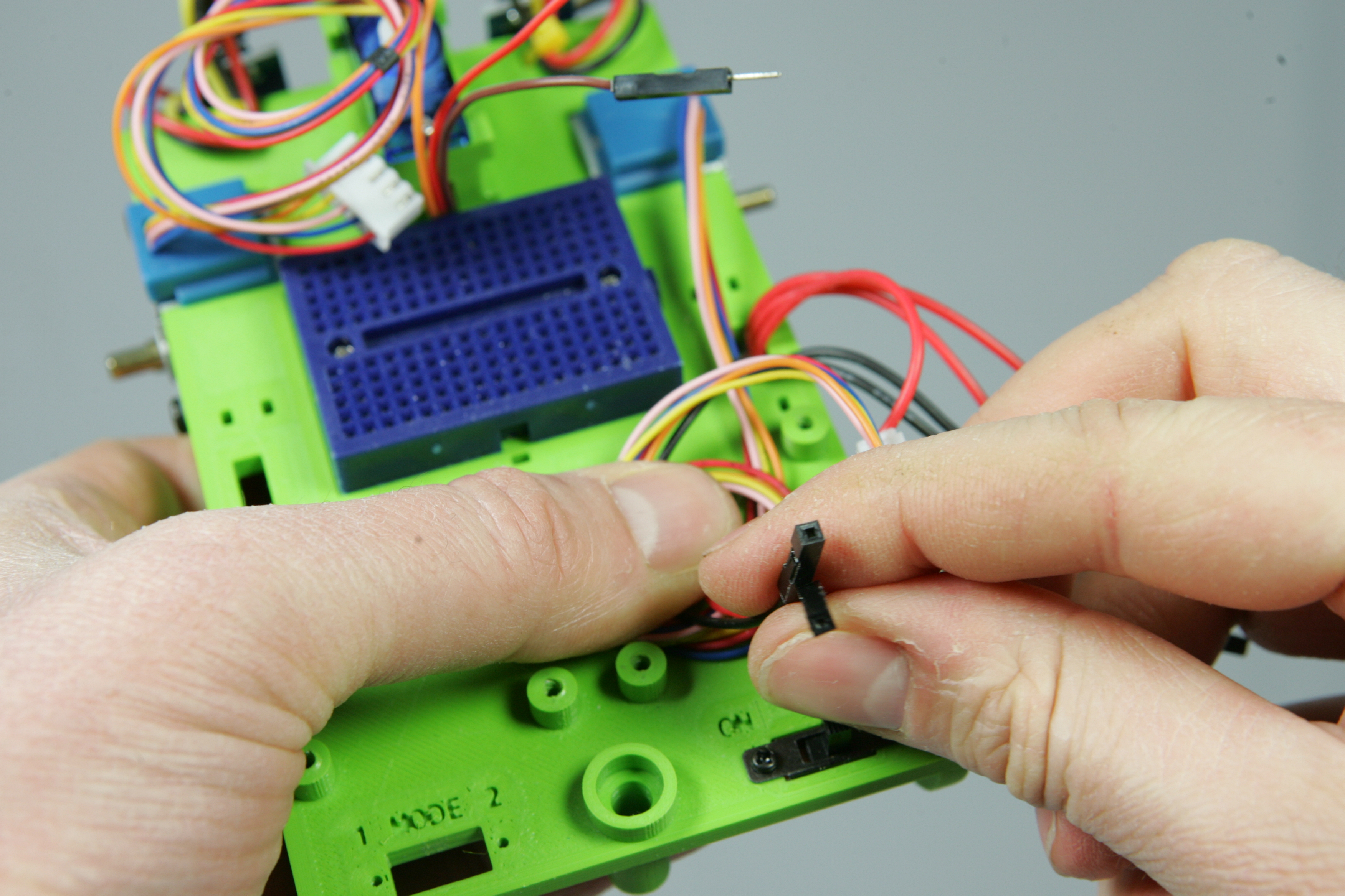
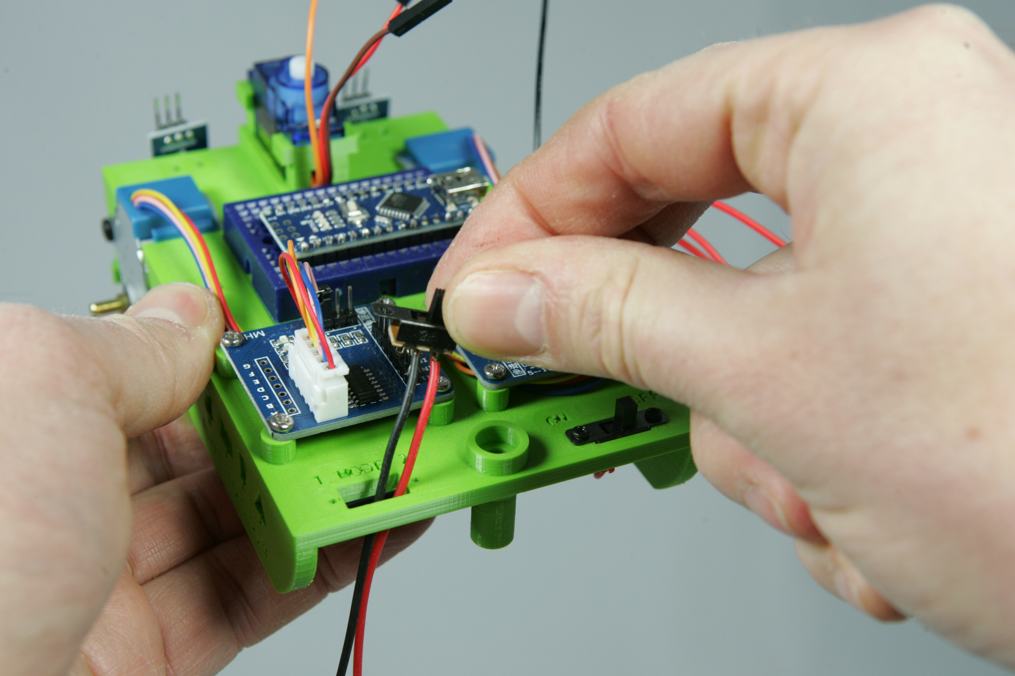
Now place the second switch from the top of the frame through the hole marked "1 MODE 2". The red wire on the switch should be on the side of the "2". Then pull the wires of the switch from the bottom of the frame through the recess of the frame on the left side. Then use two M1.7x4 screws to fasten the switch.
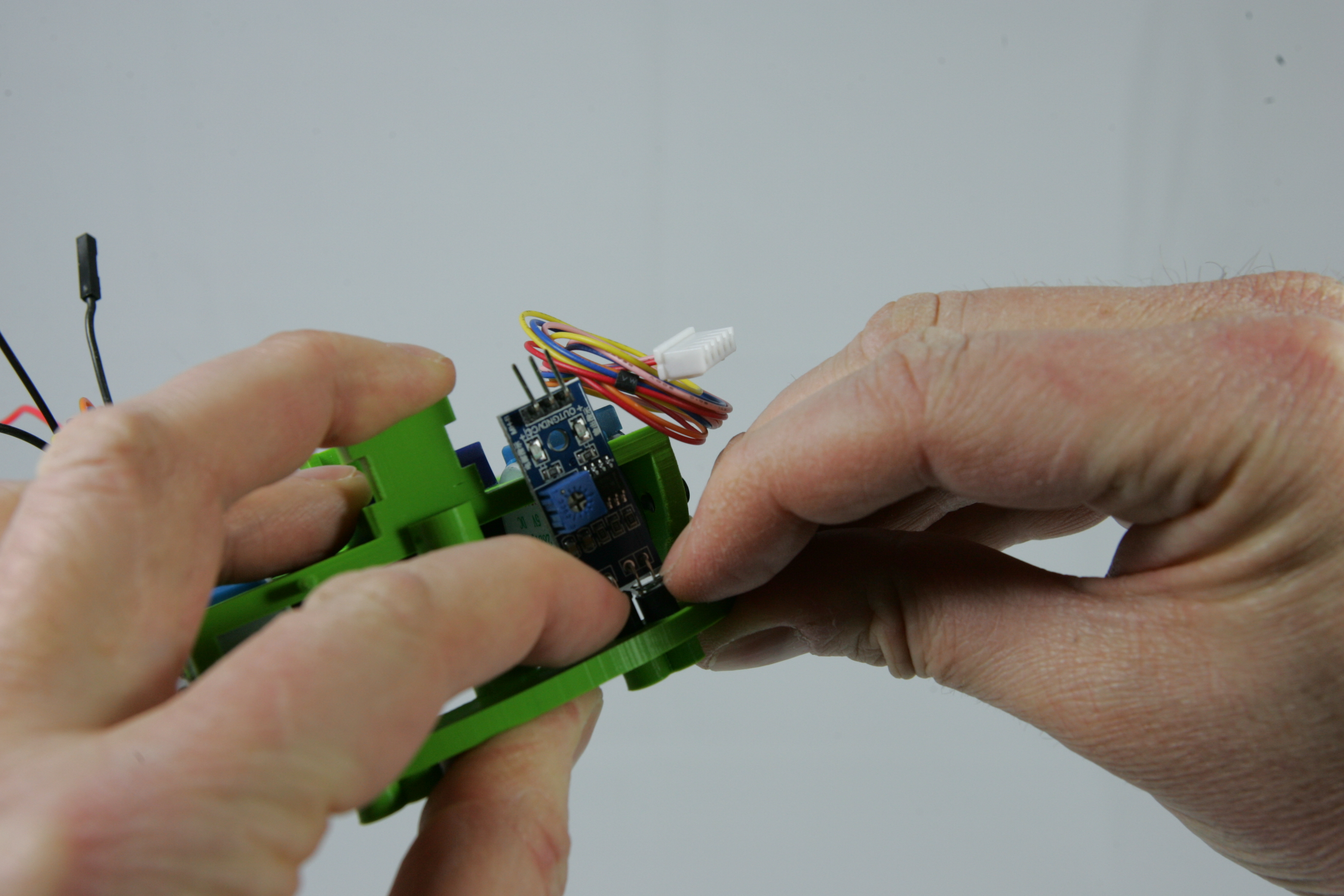
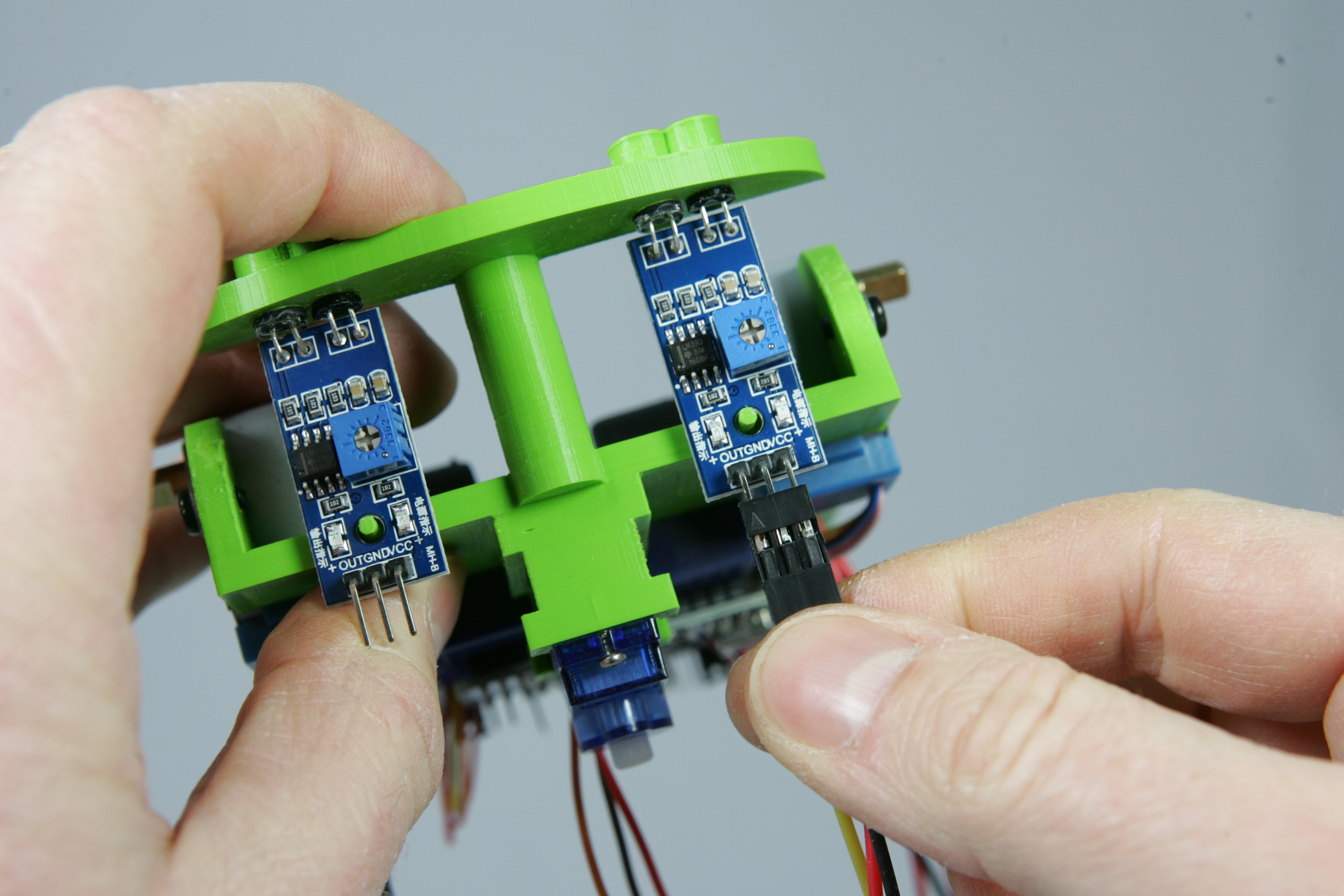
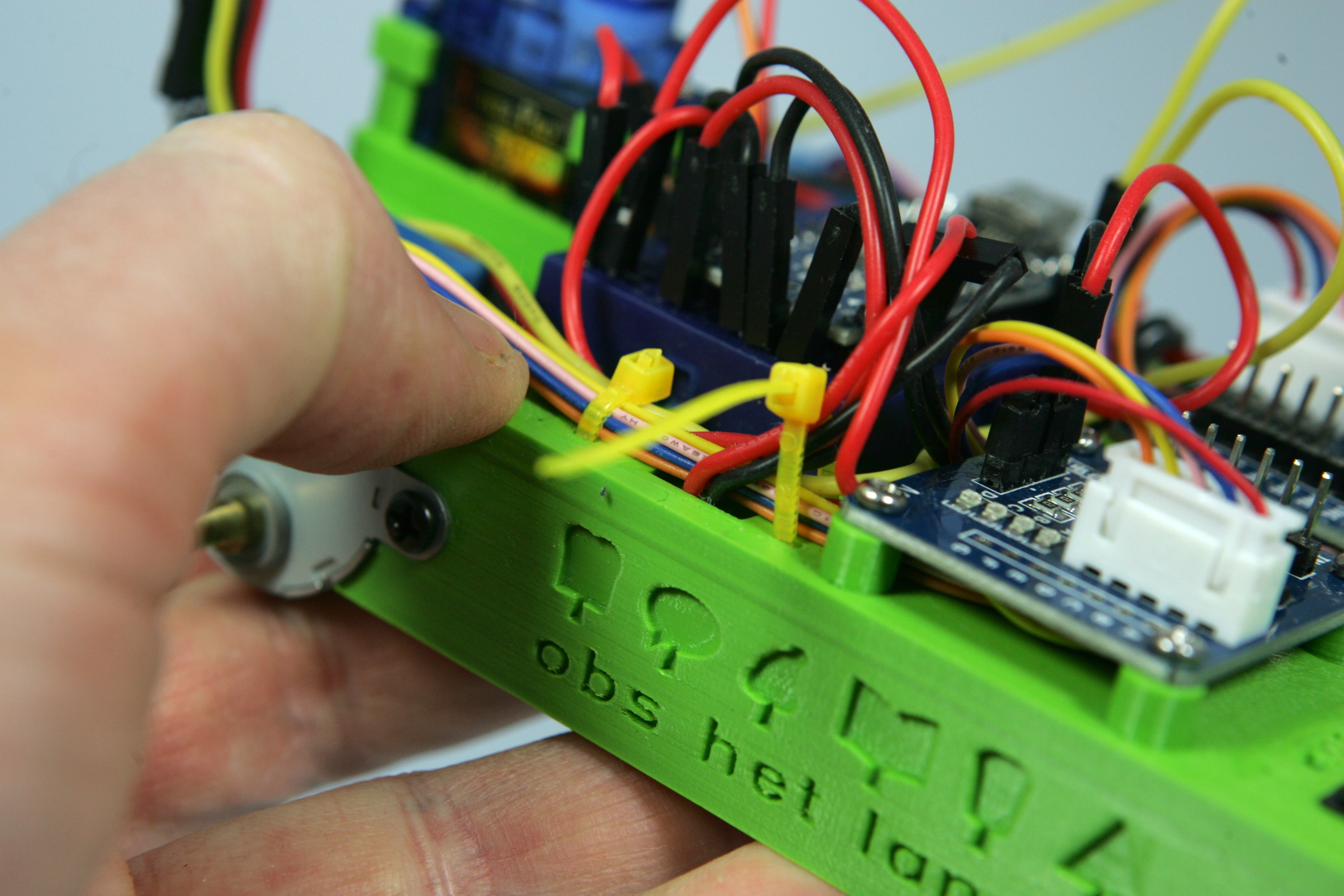
Now you are going to put the wires on the reflection sensors. Start with the right sensor. First make sure you take the right cable, the cable for the sensors are very similar. But if you look closely you can see that the red wire for the right sensor is longer.
Hold the robot frame upside down and look at the text at the pins of the sensor. You can read the labels OUT, GND and VCC. GND means the same as the - of the battery, and VCC means the +. So these pins are for the power to the sensor. With the pin OUT the sensor signals when it detects a line.
Press the connector so that the red wire is connected to the pin marked VCC and the yellow wire to the pin marked OUT.
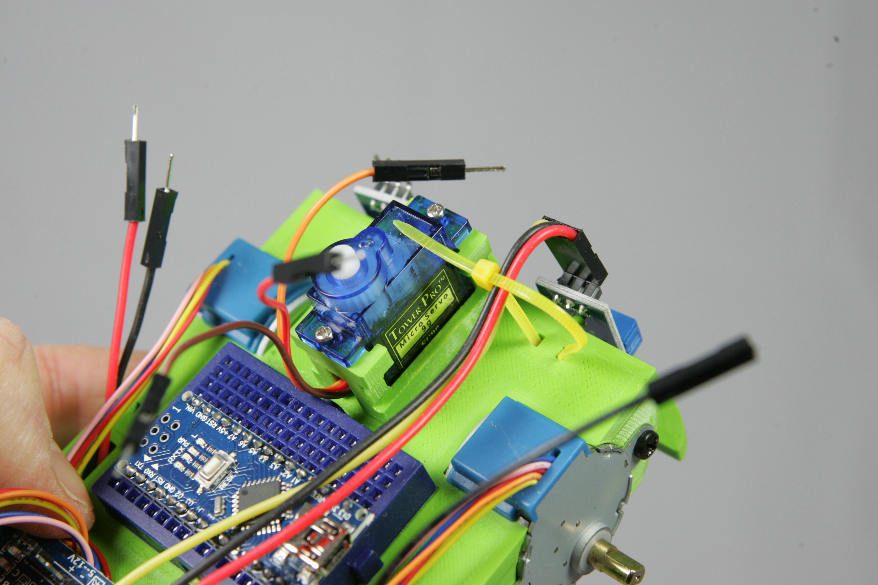
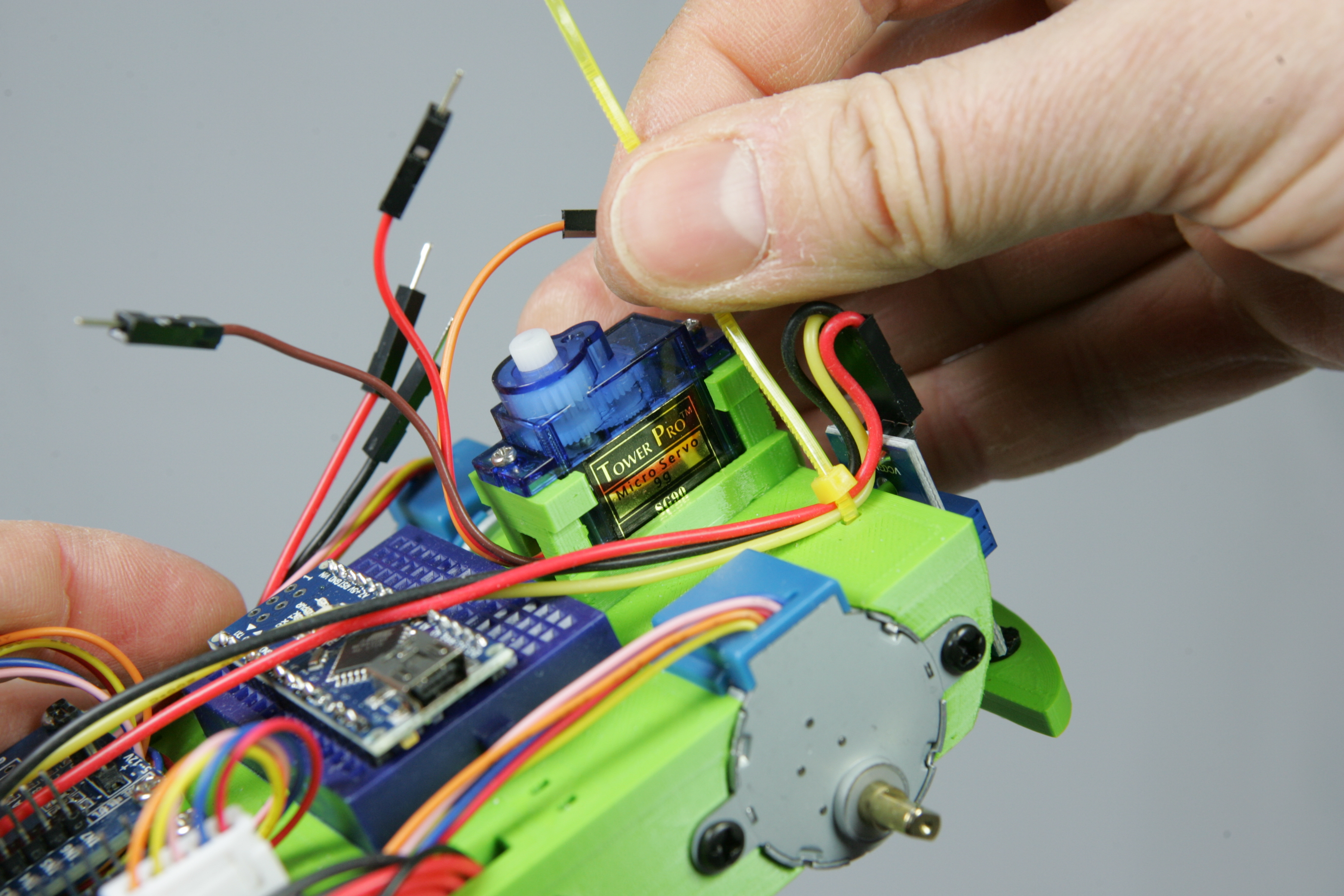
Take a cable tie and use this to fasten the cable as in the pictures below. Do not pull the cable tie too tight otherwise the cable will break.
Did you succeed? Is the cable properly connected? Nice, repeat this for the left sensor.
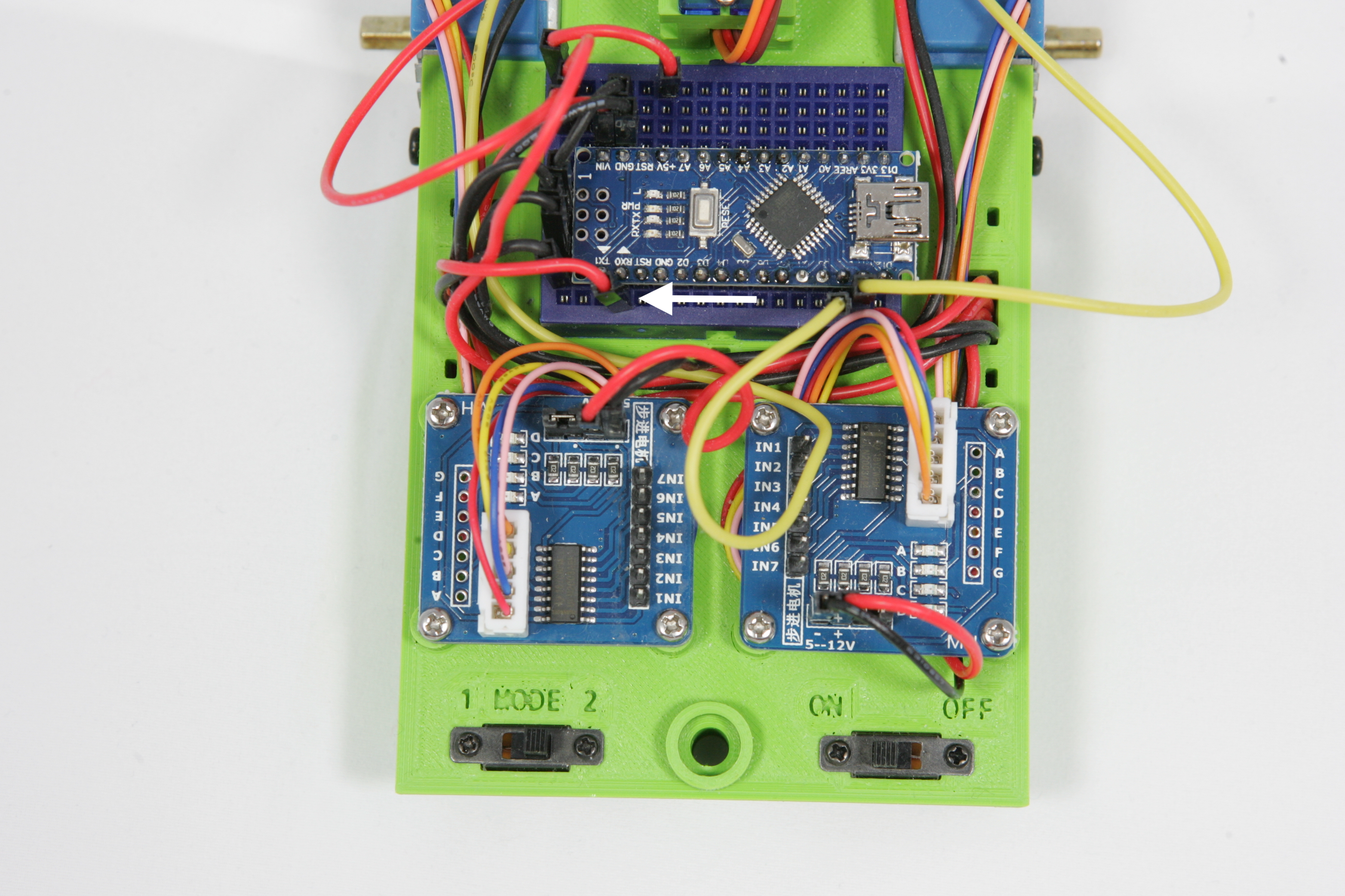
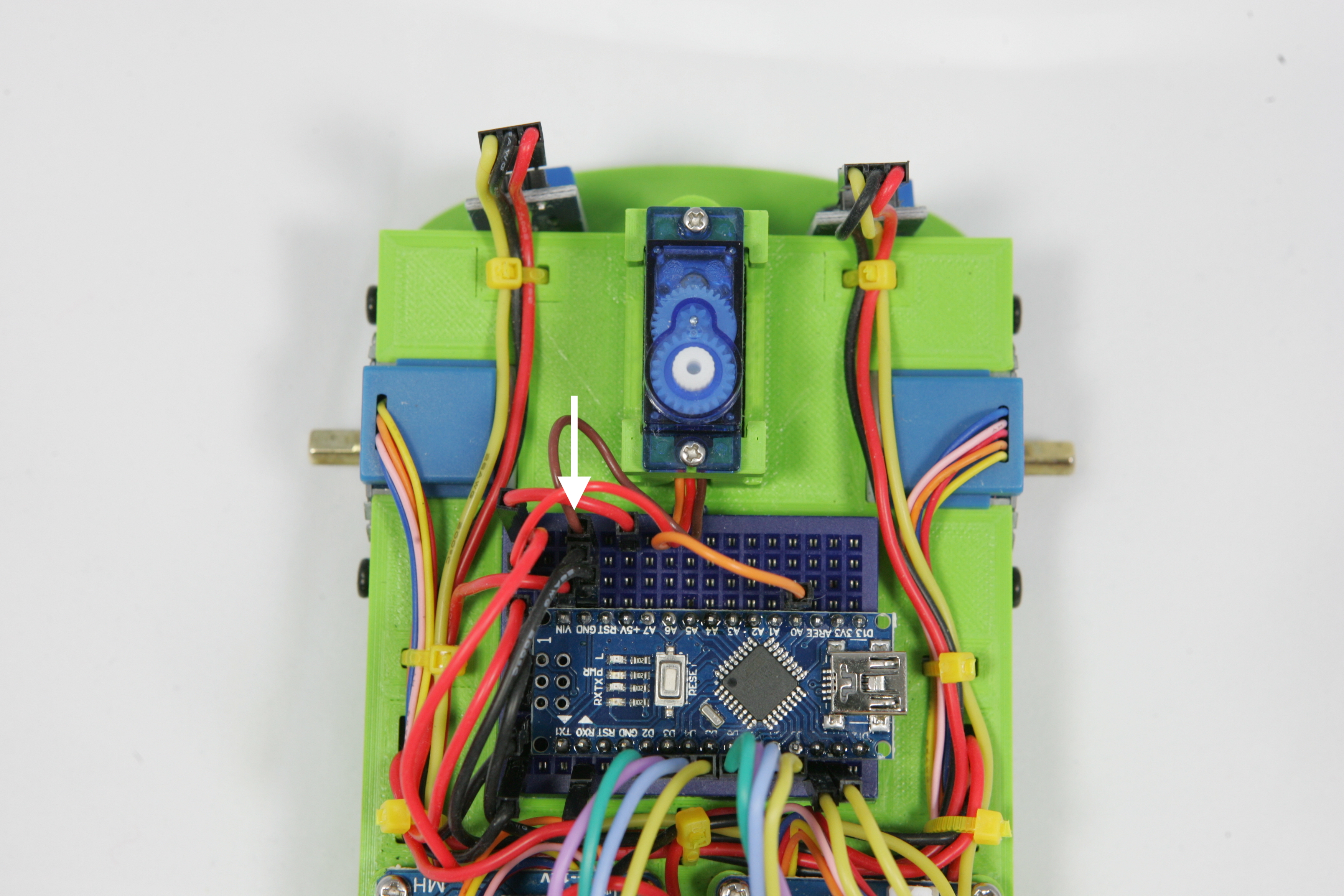
You are now going to connect the sensors, switches and motors which you have attached to the frame to the Arduino. The Arduino has a lot of connections. The pictures below show many different labels for each connection. Each label colour has its own meaning. All you have to do is look at the purple labels. These have a number from 0 to 19. Soon you will have to connect wires to one of these connections. So if the instruction says "Connect the wire to connection 0", then look up the connection with the purple label "0" and connect the wire to it.
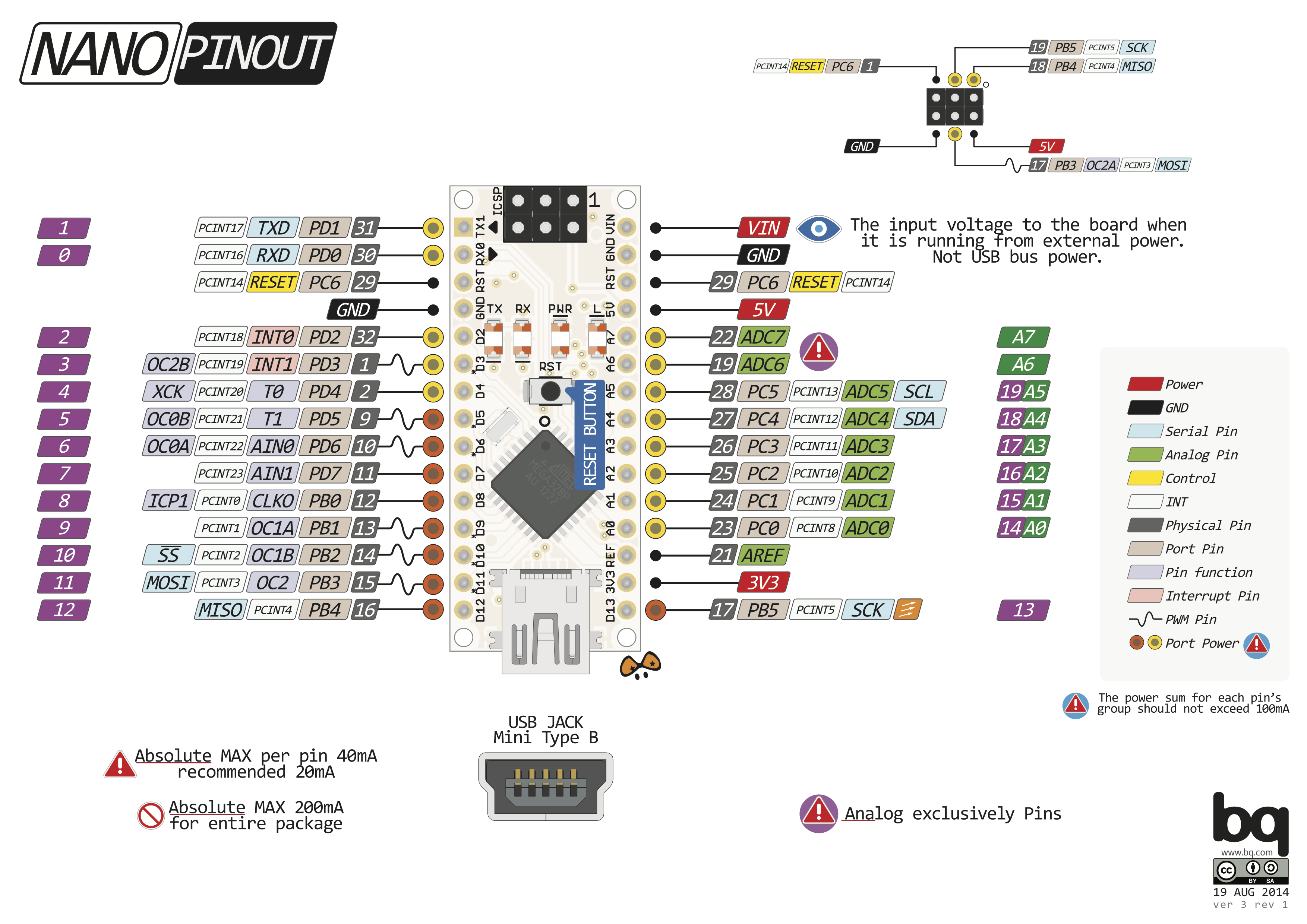
In addition to the connections with the purple labels, we are going to use three different connections of the Arduino. One of these is the connection with the label "GND". You have come across this connection before, do you remember what it is for? Another connection is "VIN", here could also have been "VCC". Do you think you already know where to connect this connection ? Finally the connection is "5V", this connection always has exactly 5 volts.
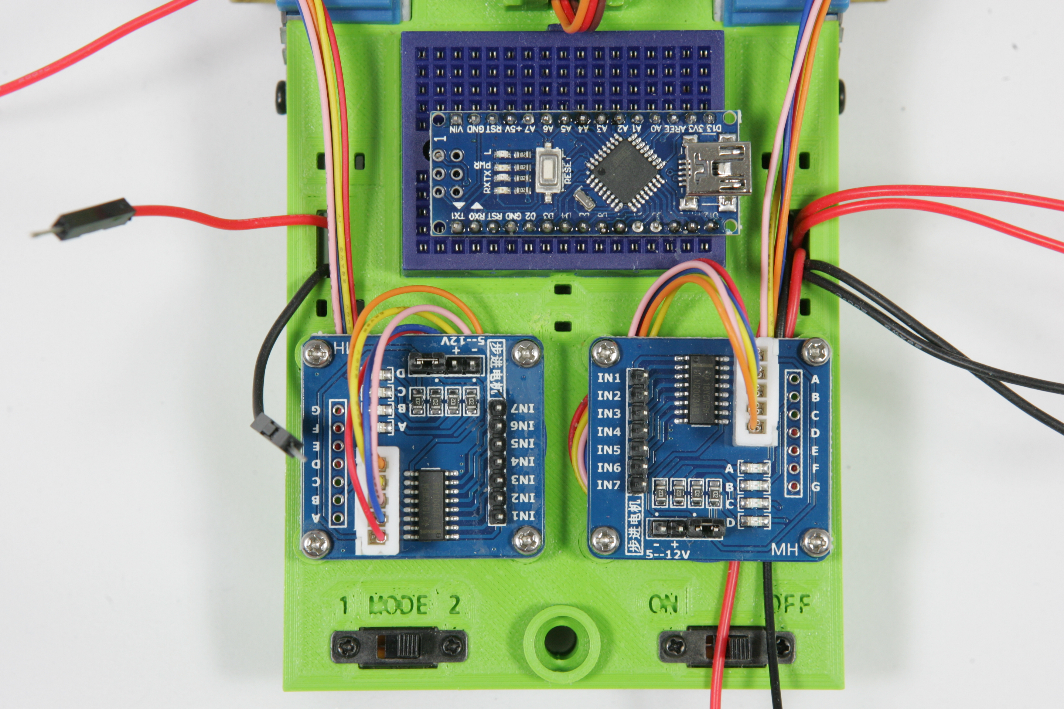
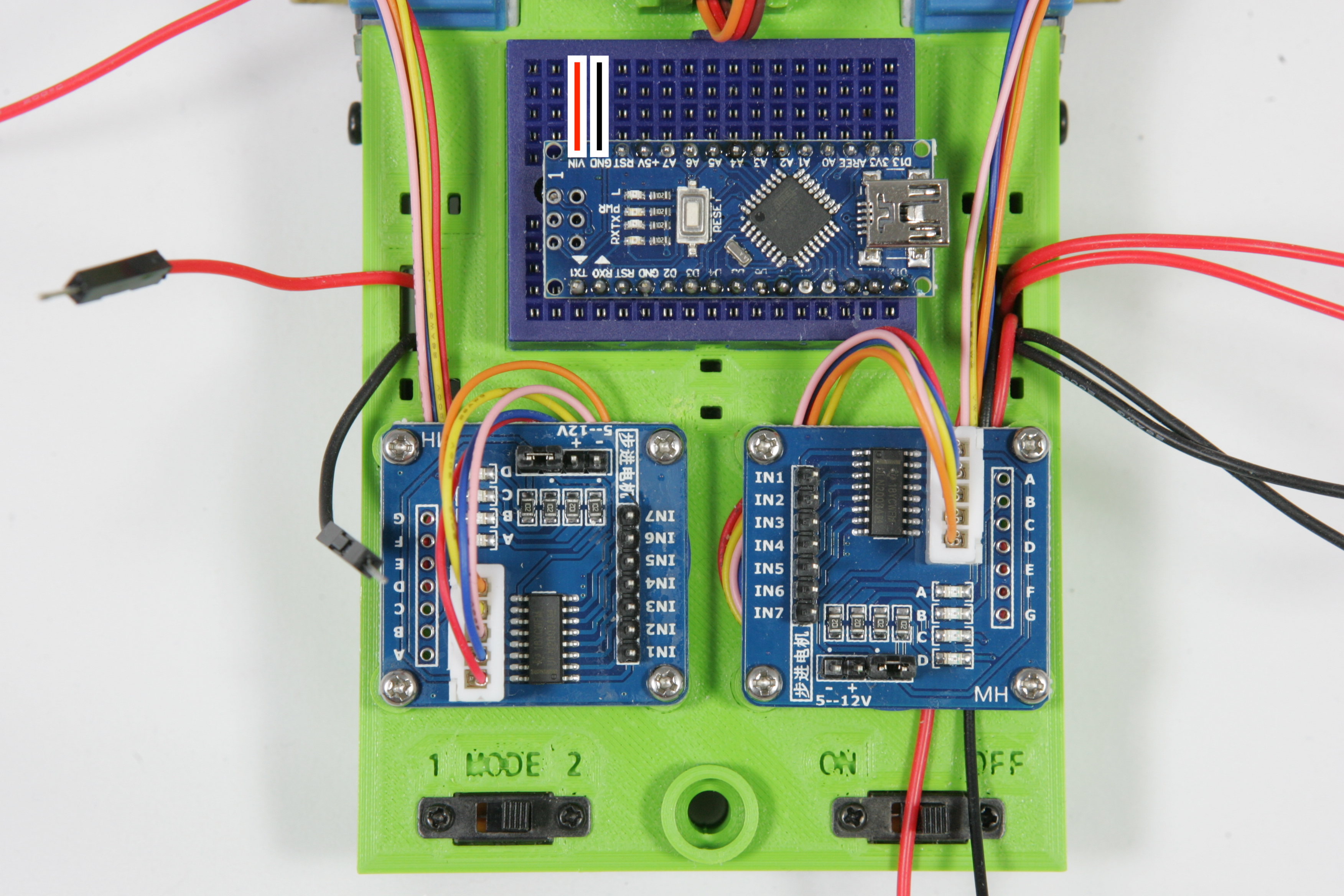
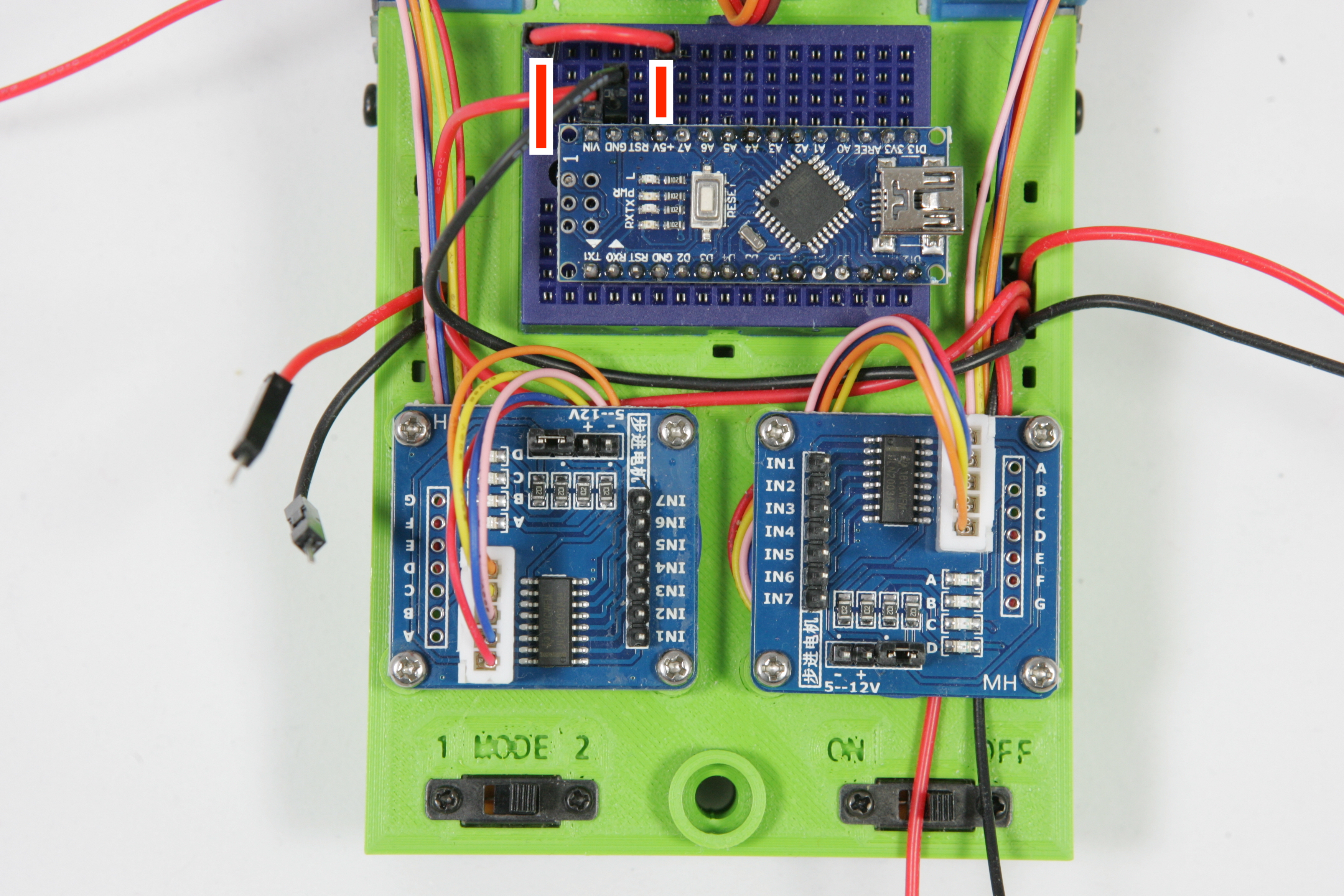
Below you can see how the Nano is fixed on your breadboard. On this breadboard there are many holes. These holes are, as shown on the picture, vertically connected to each other. This means that when you insert wires, as shown in the picture, above and below each other in the holes, they are connected to each other. There is another horizontal interruption in the middle of the breadboard, so that the top and bottom five holes are connected separately.
On the second picture on the right you see a red and black stripe. These stripes indicate how these pins are connected to each other.
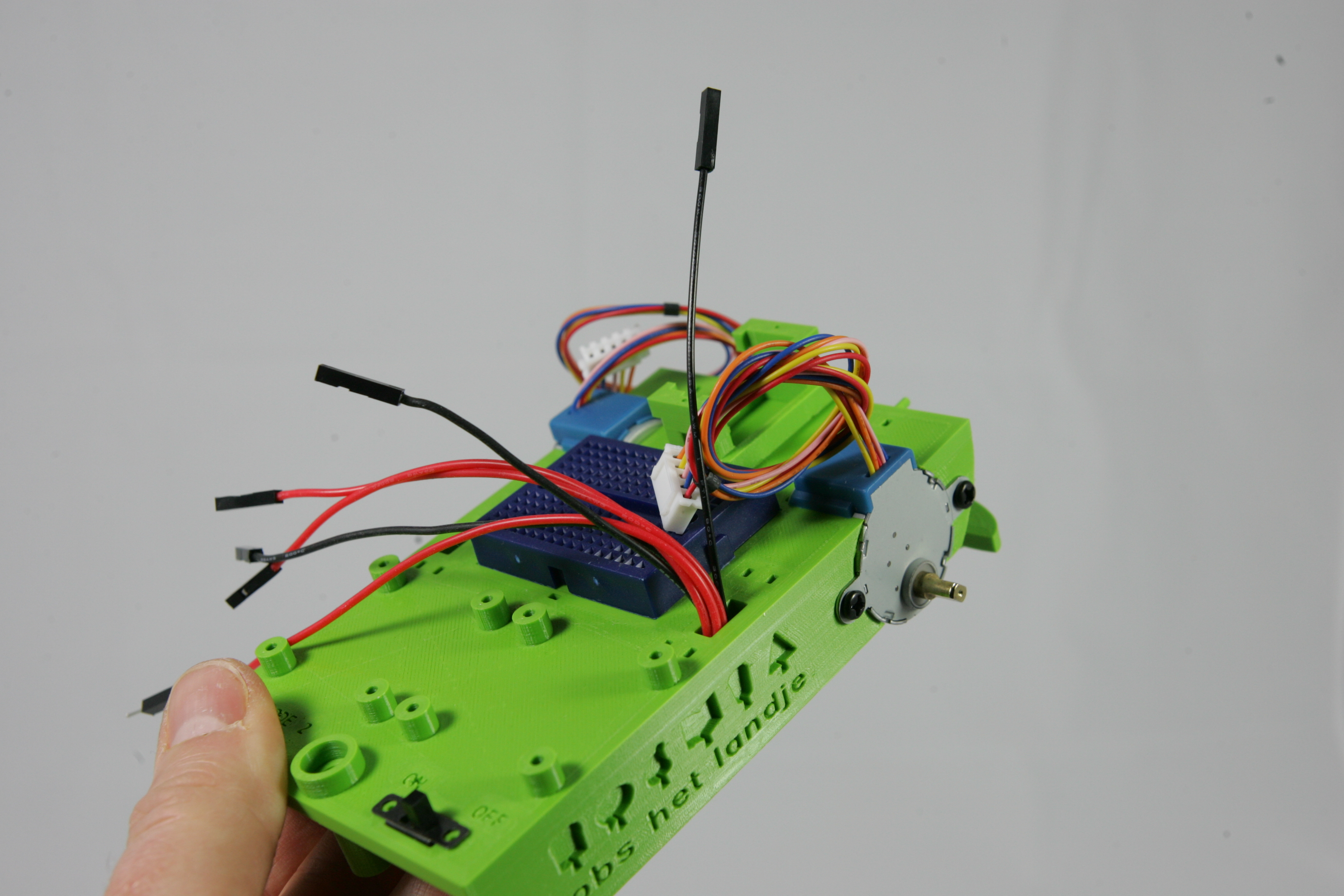
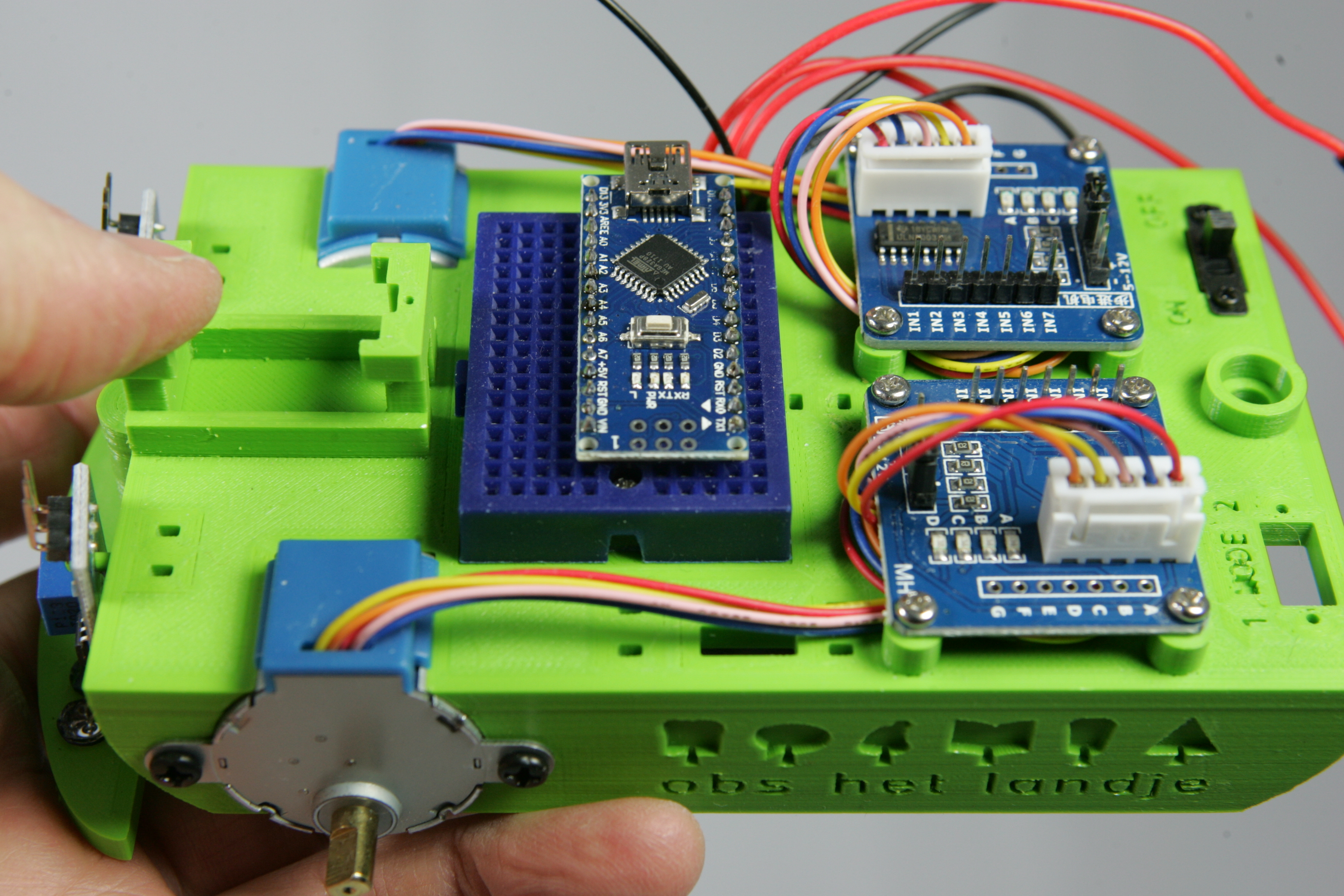
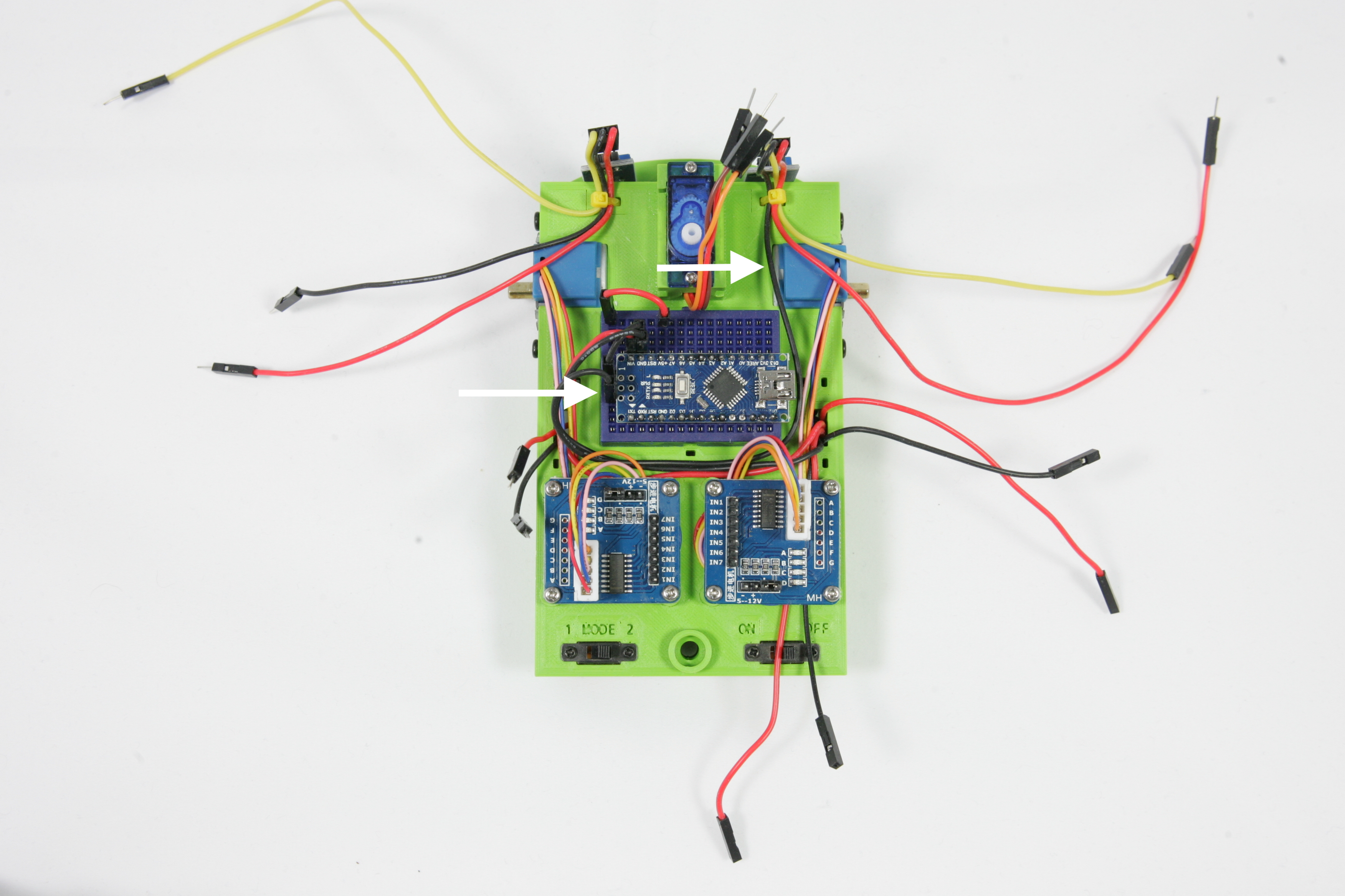
Below you see what your robot should look like now. You still have a lot of wires that are not connected. We are going to connect these wires step by step to the breadboard so that all parts are connected to the Arduino. The picture shows a label for each wire. These labels will later be used to make clear which wire has to be placed in the breadboard.
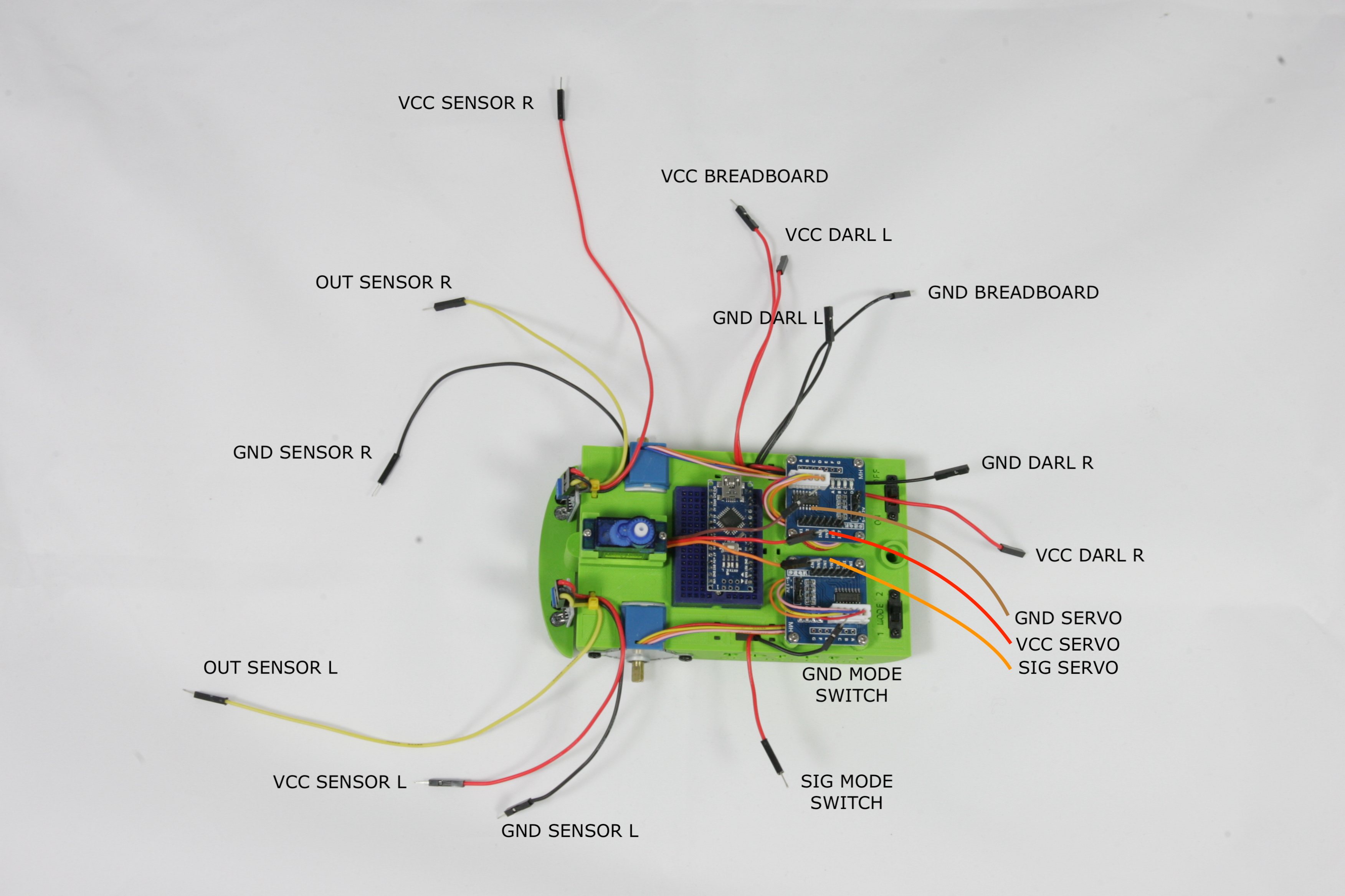
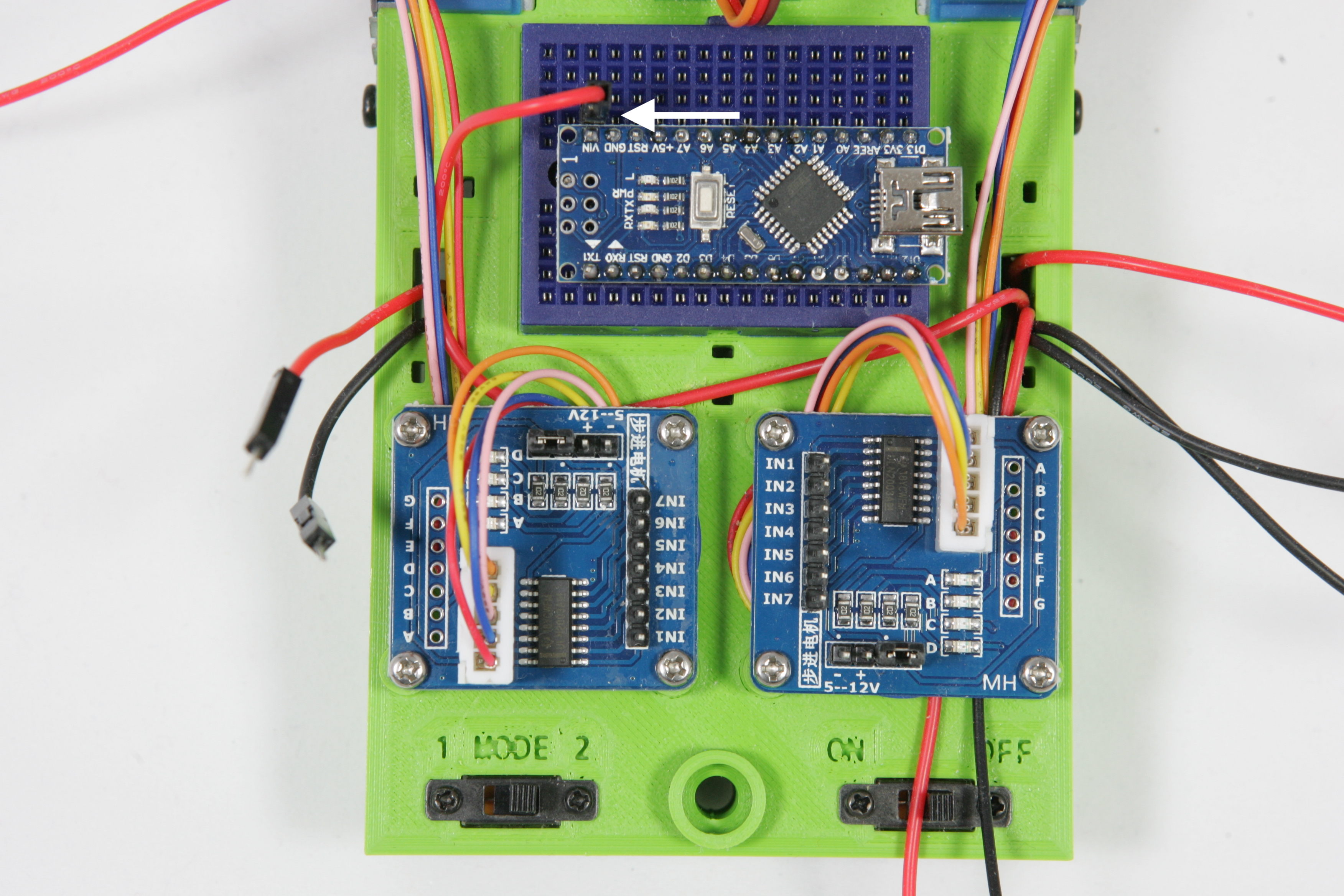
We start by connecting the power supply, the electricity, for the sensors and computer. Without power a computer cannot work. Take the VCC BREADBOARD wire and place it in the breadboard so that it is connected to VCC of the Arduino.
Place the wire GND BREADBOARD and connect it to the GND connection on the Arduino. Look carefully at the pictures and make sure the wires are neat as shown. Soon we will fix the wires so that it doesn't become messy.
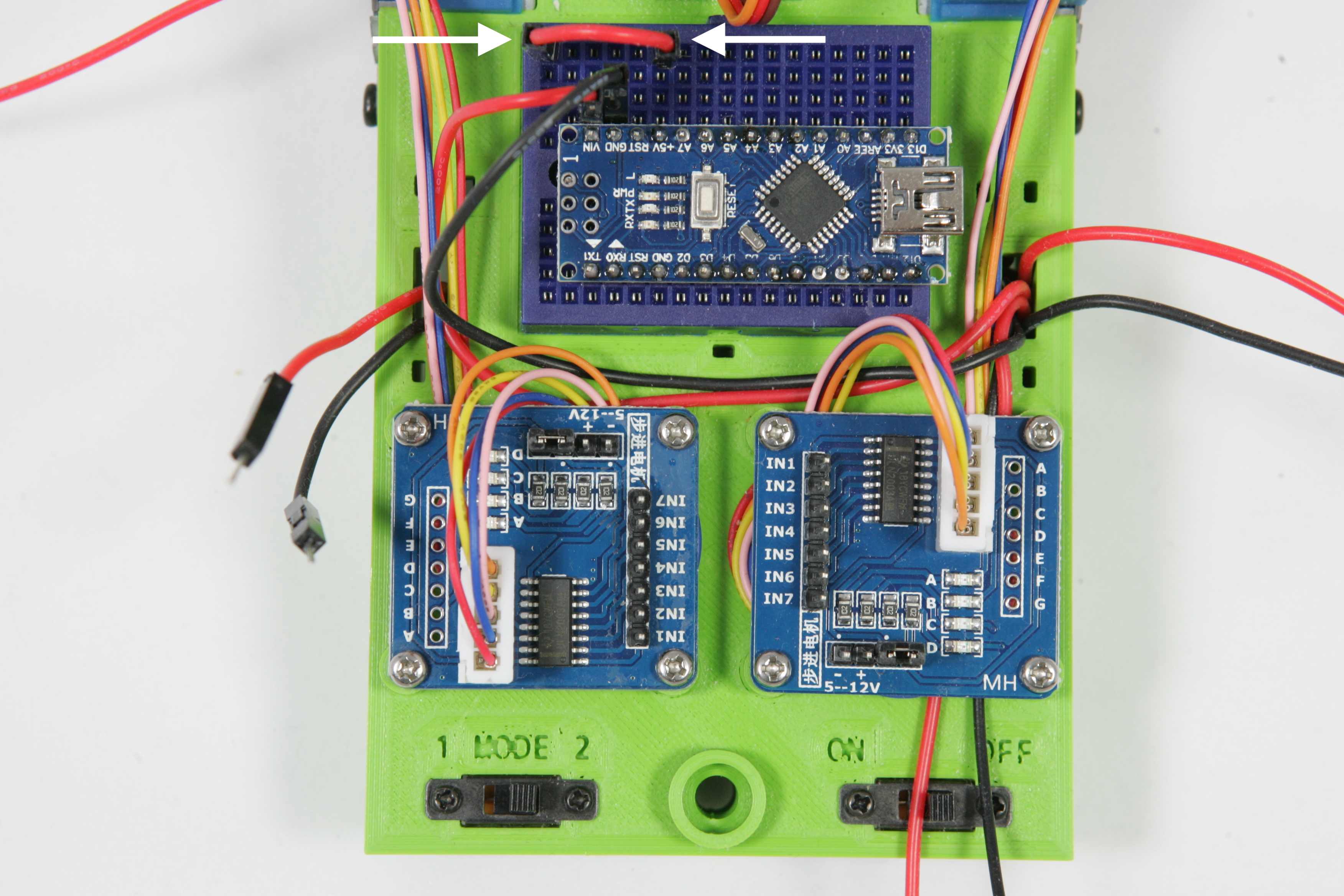
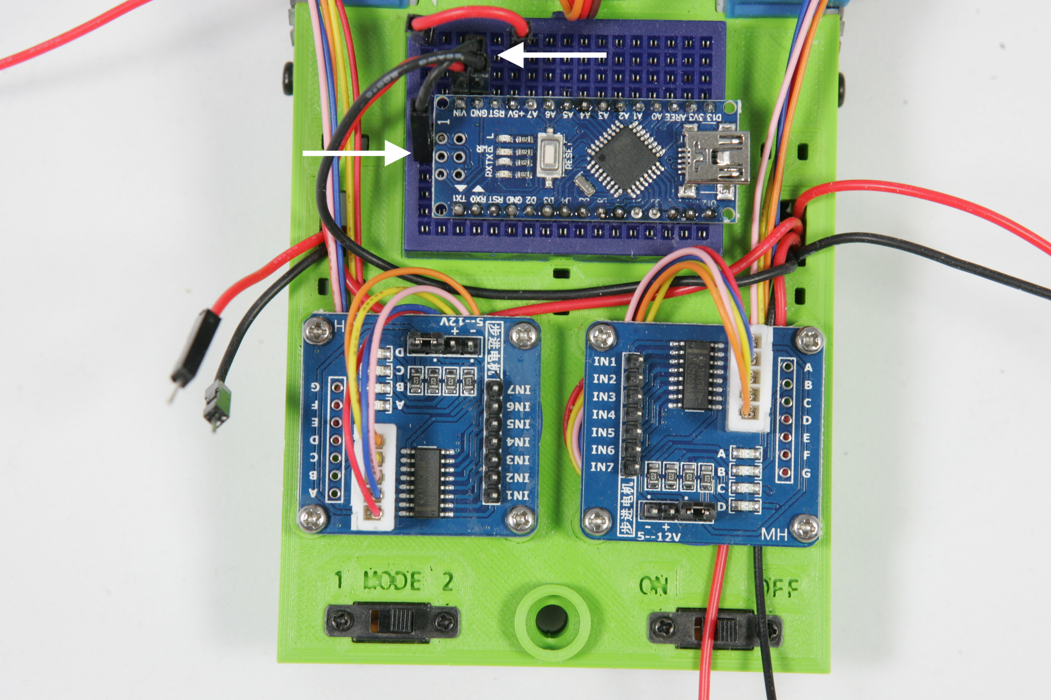
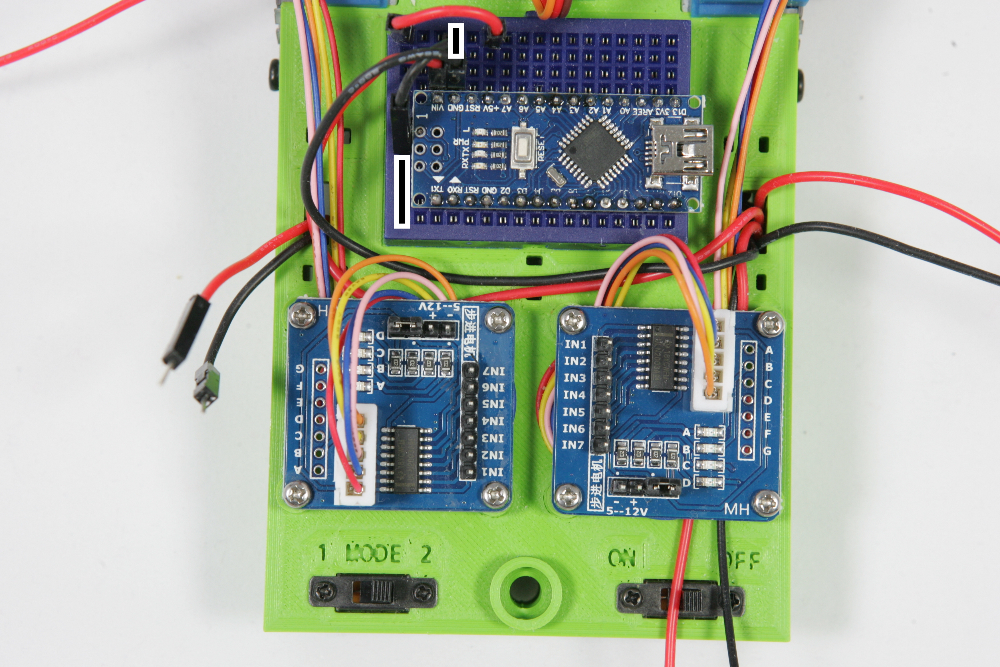
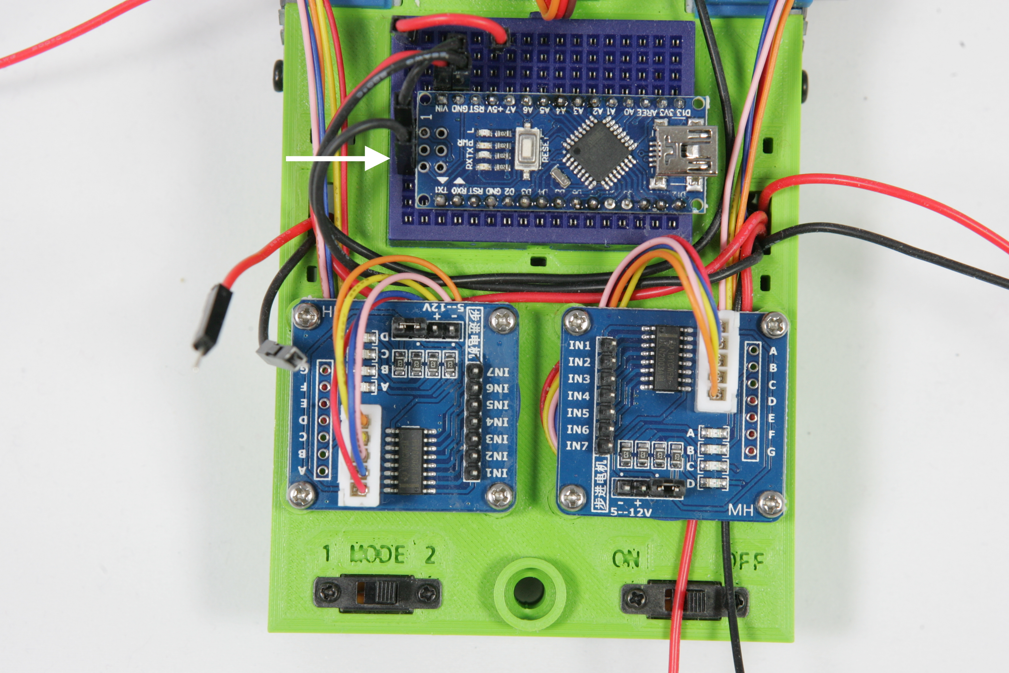
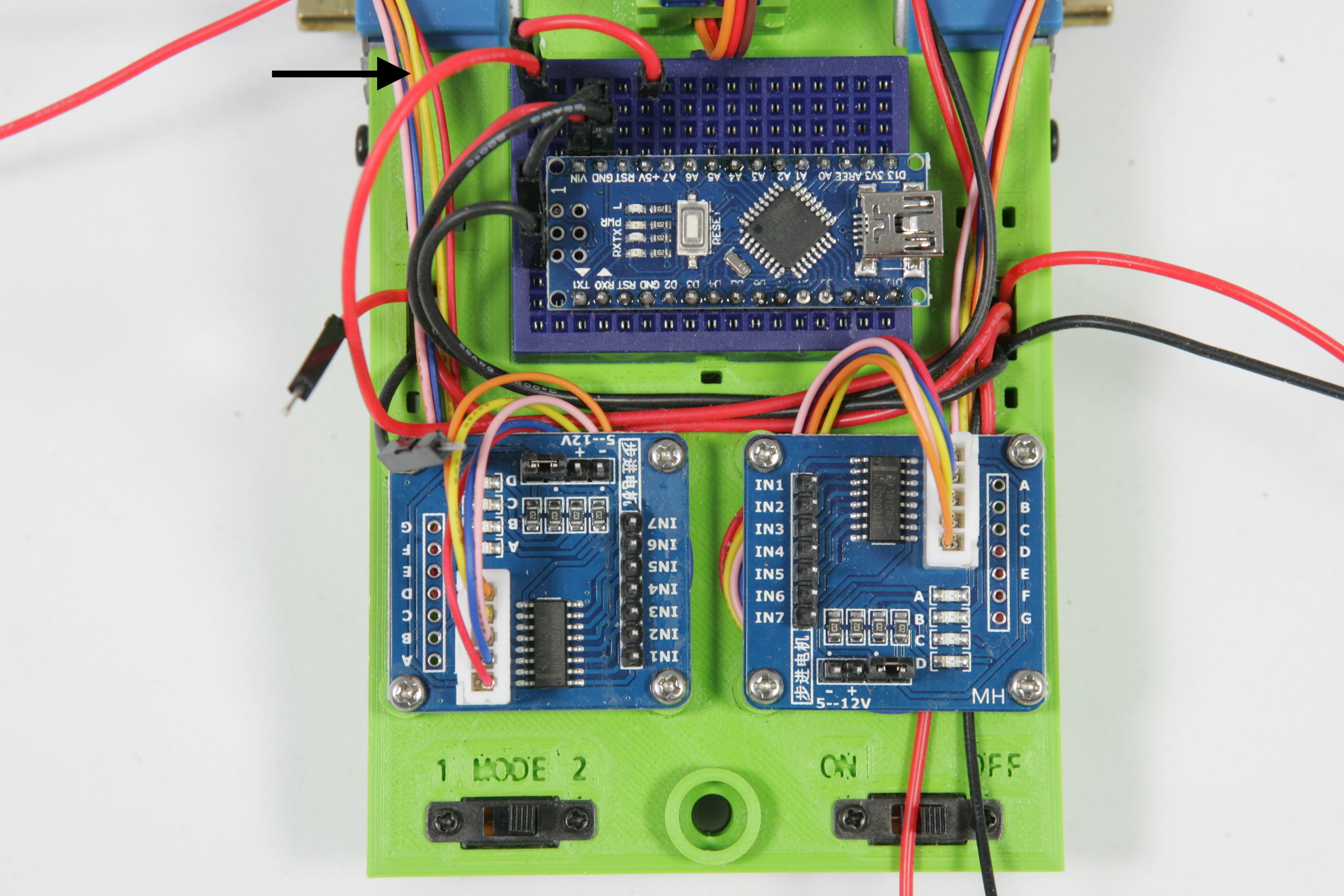
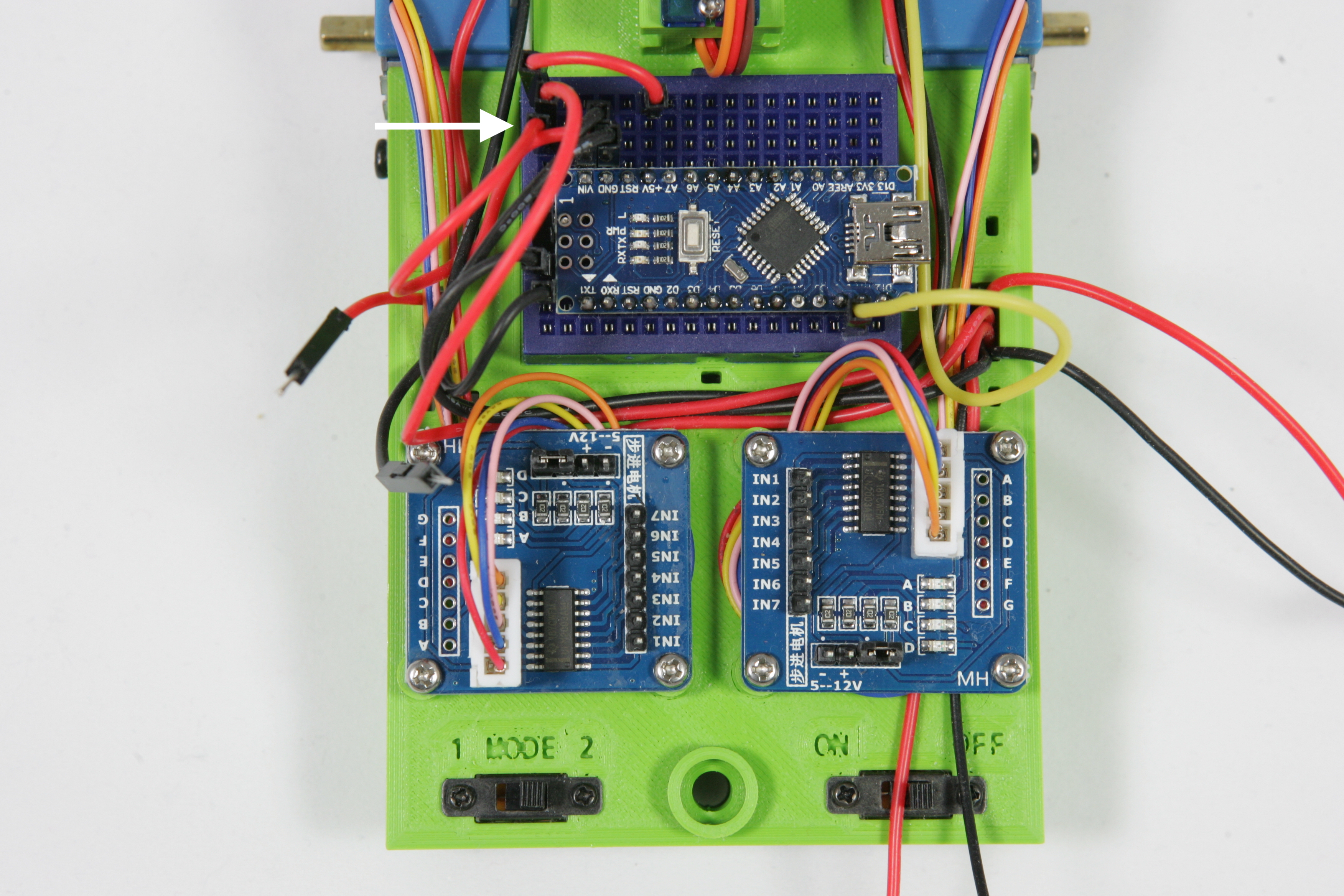
On the Arduino there is a +5V connection. When the Arduino is connected, this connection always produces exactly 5 volts. Because we need to connect more than 4 wires to +5V we will wire this connection to a free row on the breadboard. Take the red short connection wire and connect the +5V of the Arduino with the top left row on the breadboard as shown in the left picture below. You now have 7 instead of 4 connections with +5V. These connections are indicated with a red line on the picture below right.
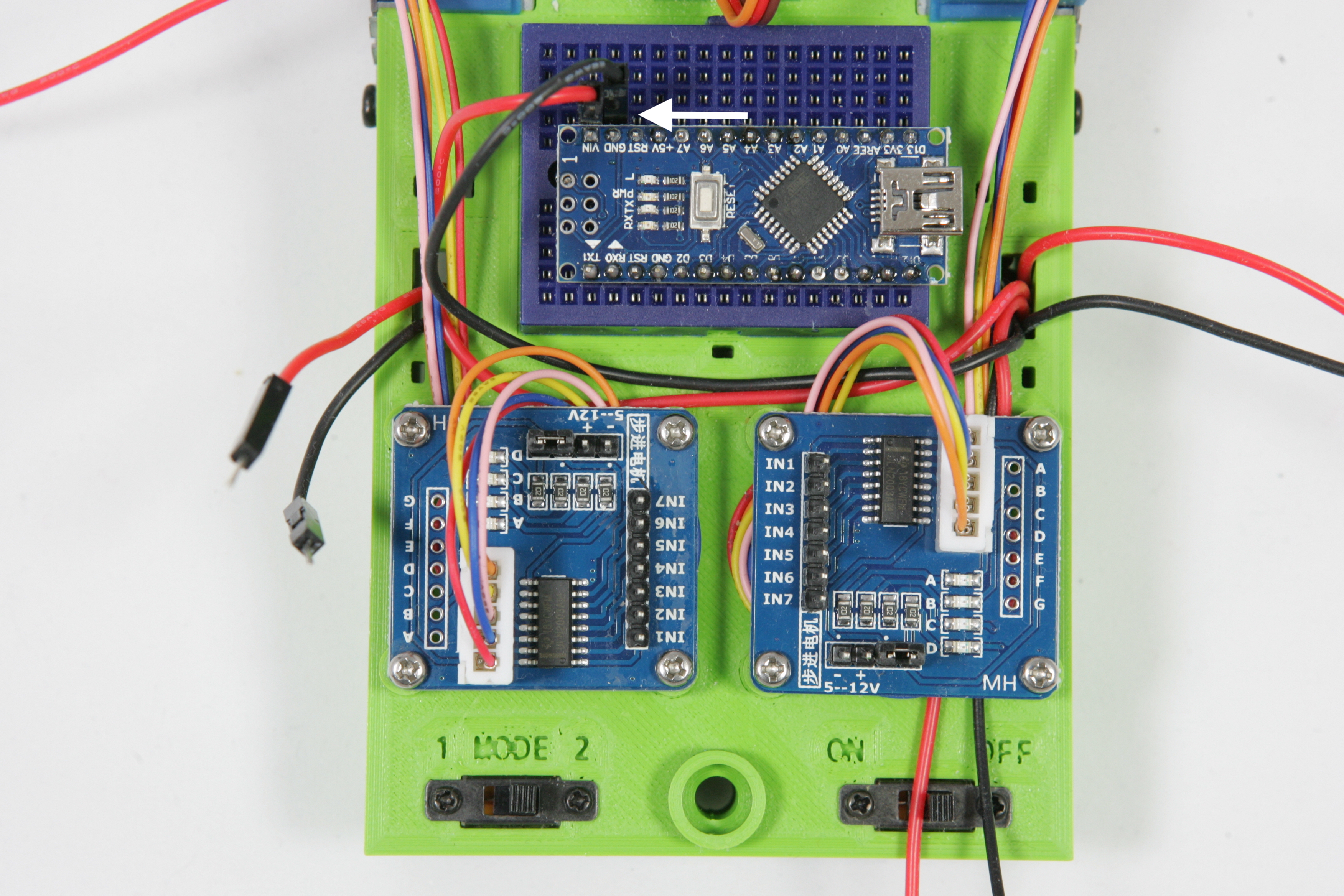
We will now repeat what we did for the +5V for the GND connection on the Arduino. Take the short black wire and connect the GND connector on the Arduino with the lower left row on the breadboard. You now have 6 instead of 4 connections with GND. These connections are marked with a black line on the picture below right.
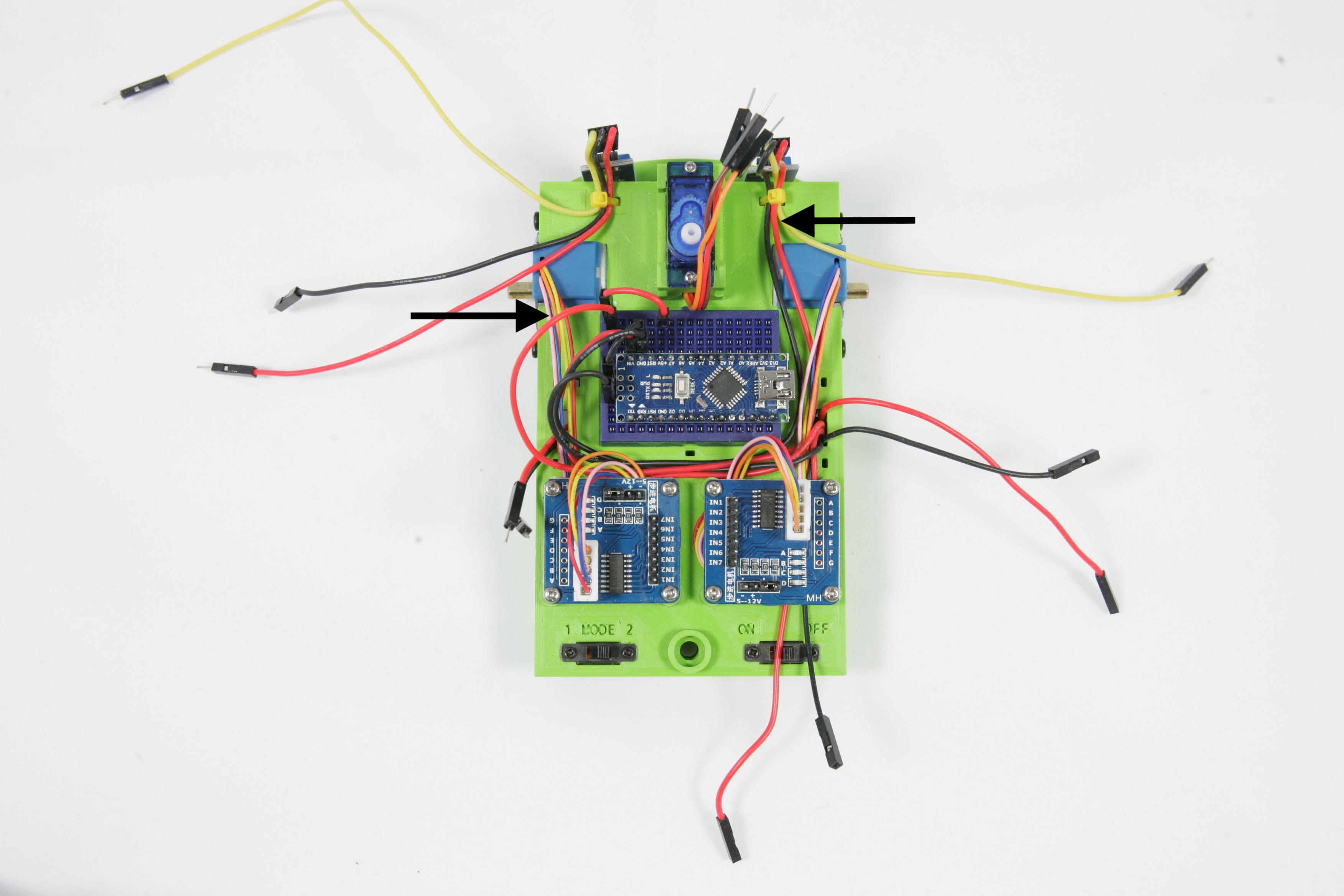
The reflection sensors need 5 volts to work. In the previous steps you connected GND and 5V to the left two rows of the breadboard. Now you are going to connect the sensor to these two rows so the sensor will be powered. Take the black GND SENSOR Rwire from the right reflection sensor and place it in one of the holes in the bottom left corner of the breadboard that is connected to GND of the Arduino. Take a good look at the pictures below to see how the wire was laid along the Arduino.
When the sensor is connected to GND the sensor must still be connected to 5V. Place the red VCC SENSOR R wire from the right reflection sensor as shown on the pictures below around the Arduino. Then place the pin in the top left row of the breadboard connected to the 5V connection of the Arduino.
.One more wire from the right reflection sensor is not connected, the OUT SENSOR R. This wire gives a signal to the Arduino when it detects a reflection. This wire must be connected to connection 11 of the Arduino.
Now you have to repeat what you did for the right sensor for the left reflection sensor. Connect the GND SENSOR L and VCC SENSOR L wire of the sensor as with the right sensor. Take a good look at the pictures below.
Also the wire OUT SENSOR L of the left reflection sensor must be connected. Connect this wire to connection 10 of the Arduino.
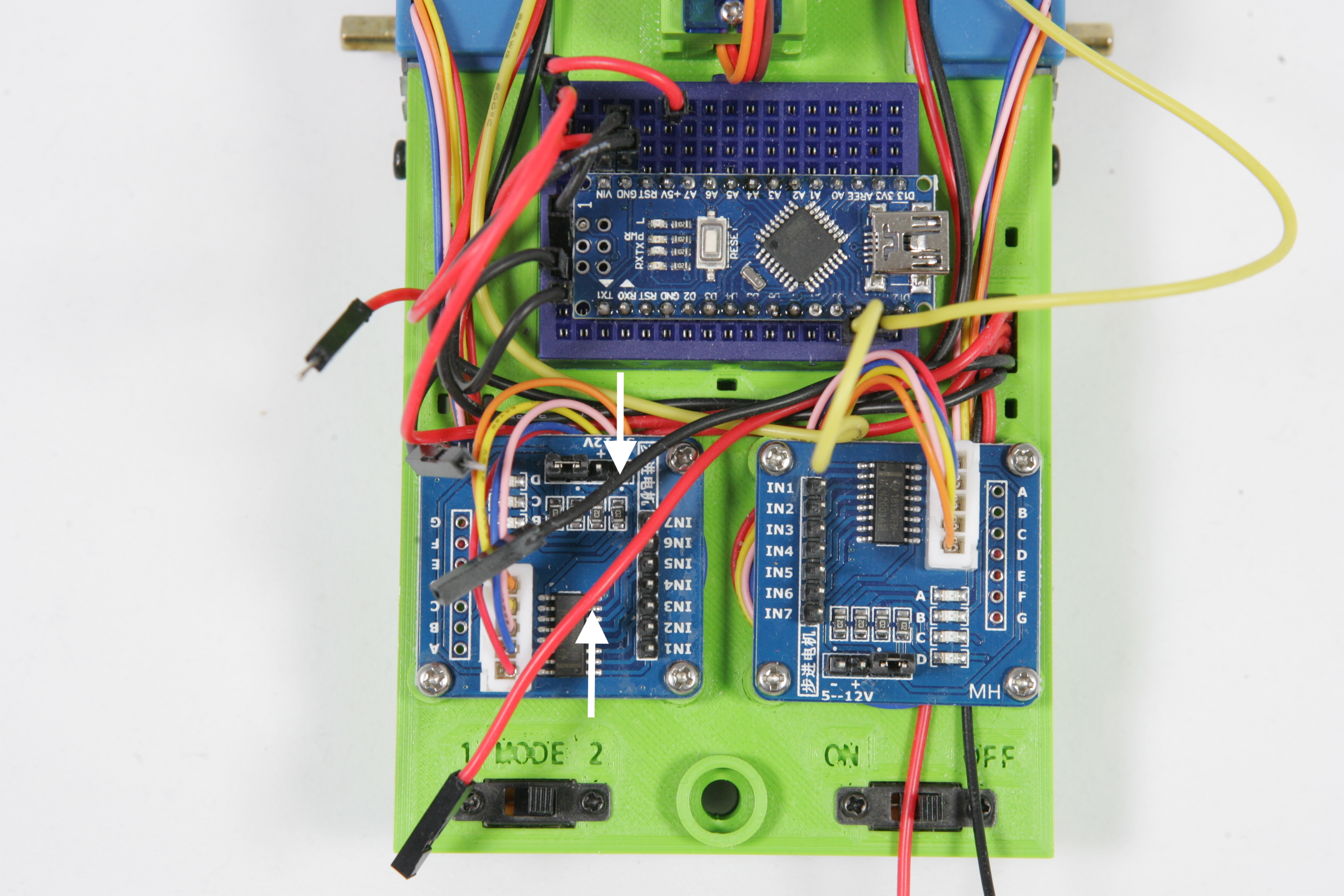
Both sensors are now connected. Now you connect the power supply to the Darlington drivers so that the two stepper motors can run later. If all goes well two wires of the battery should stick out of the opening of the frame, VCC DARL L and GND DARL L. Take these two wires and place them under the Arduino to the left Darlington driver.
Connect the wire GND DARL L to the pin with the text '-' and VCC DARL L on the '+'.
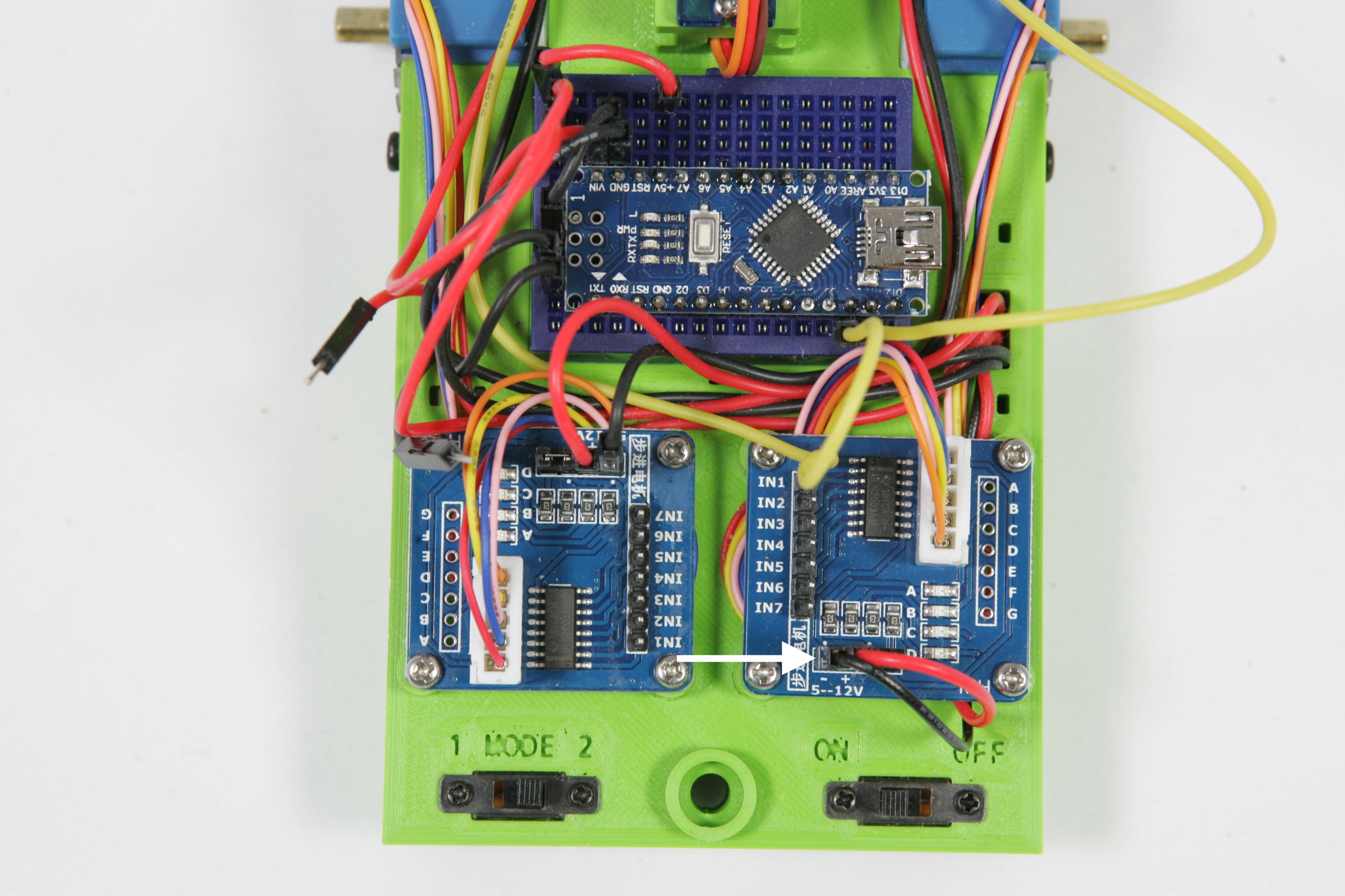
Connect now the same wires for the right Darlington driver to the '-' and the '+'. These are the wires VCC DARL R and GND DARL R.
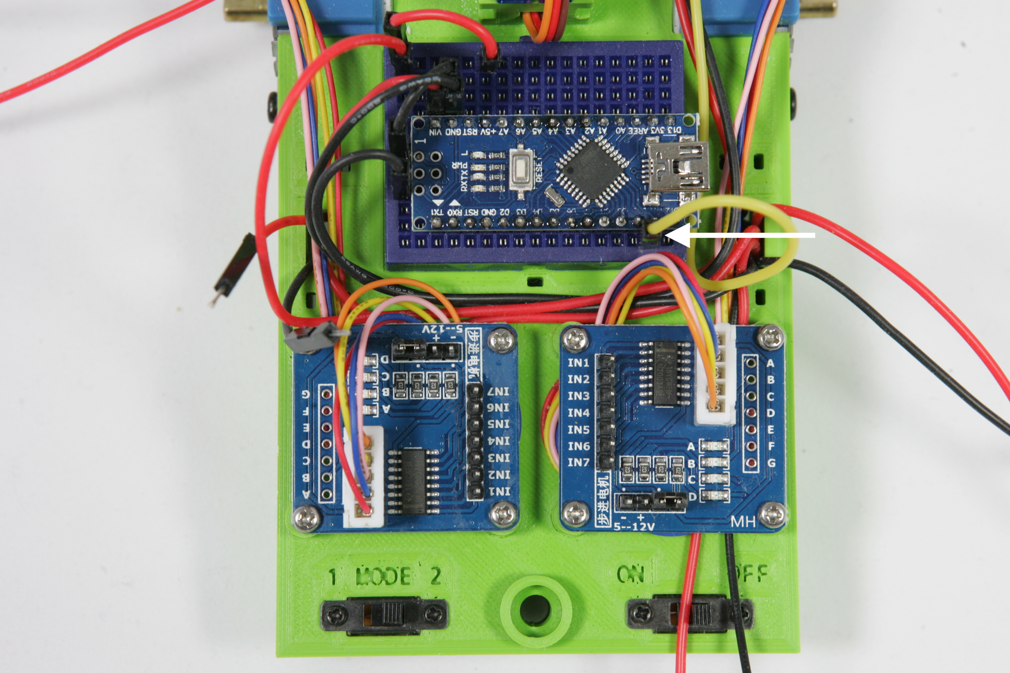
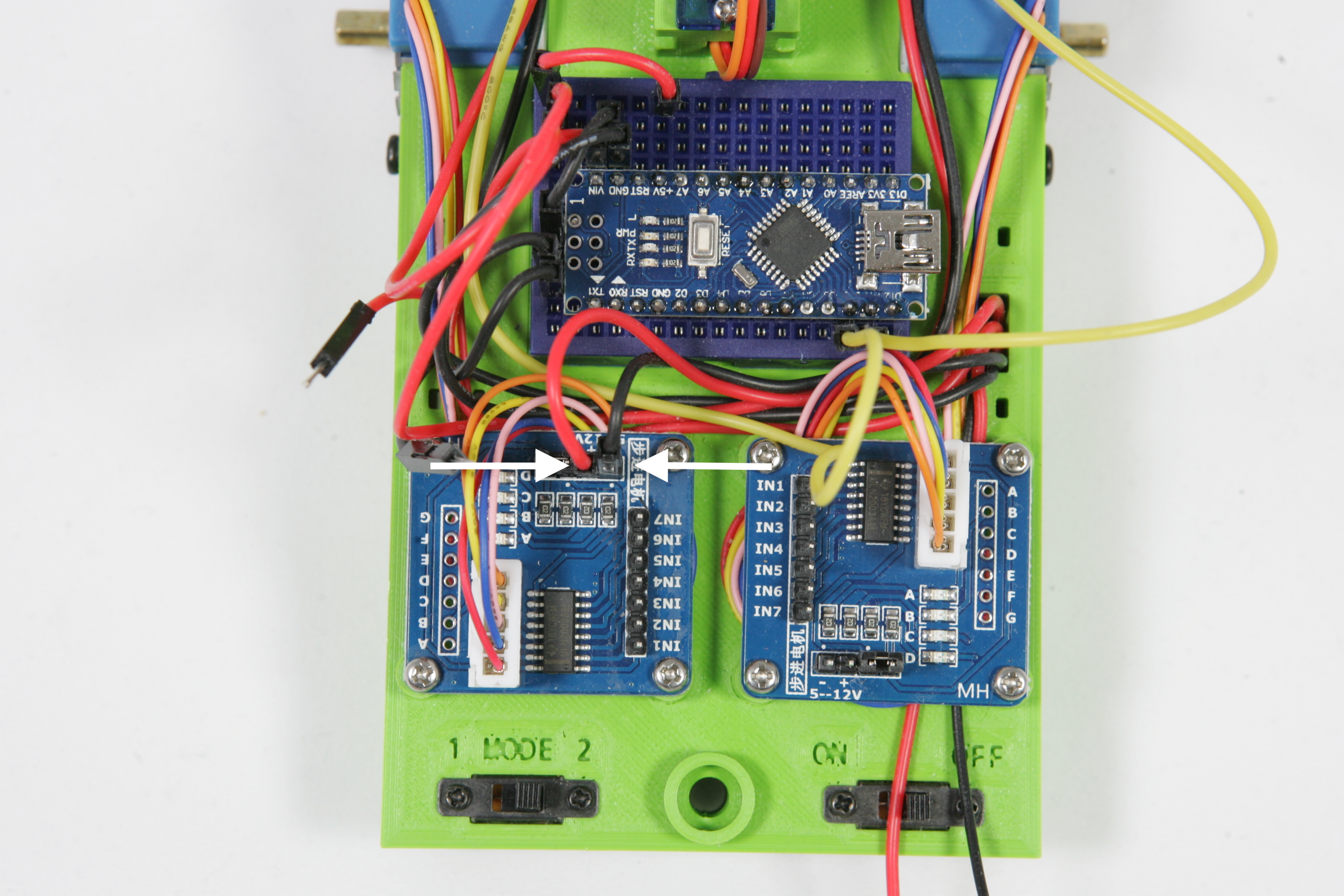
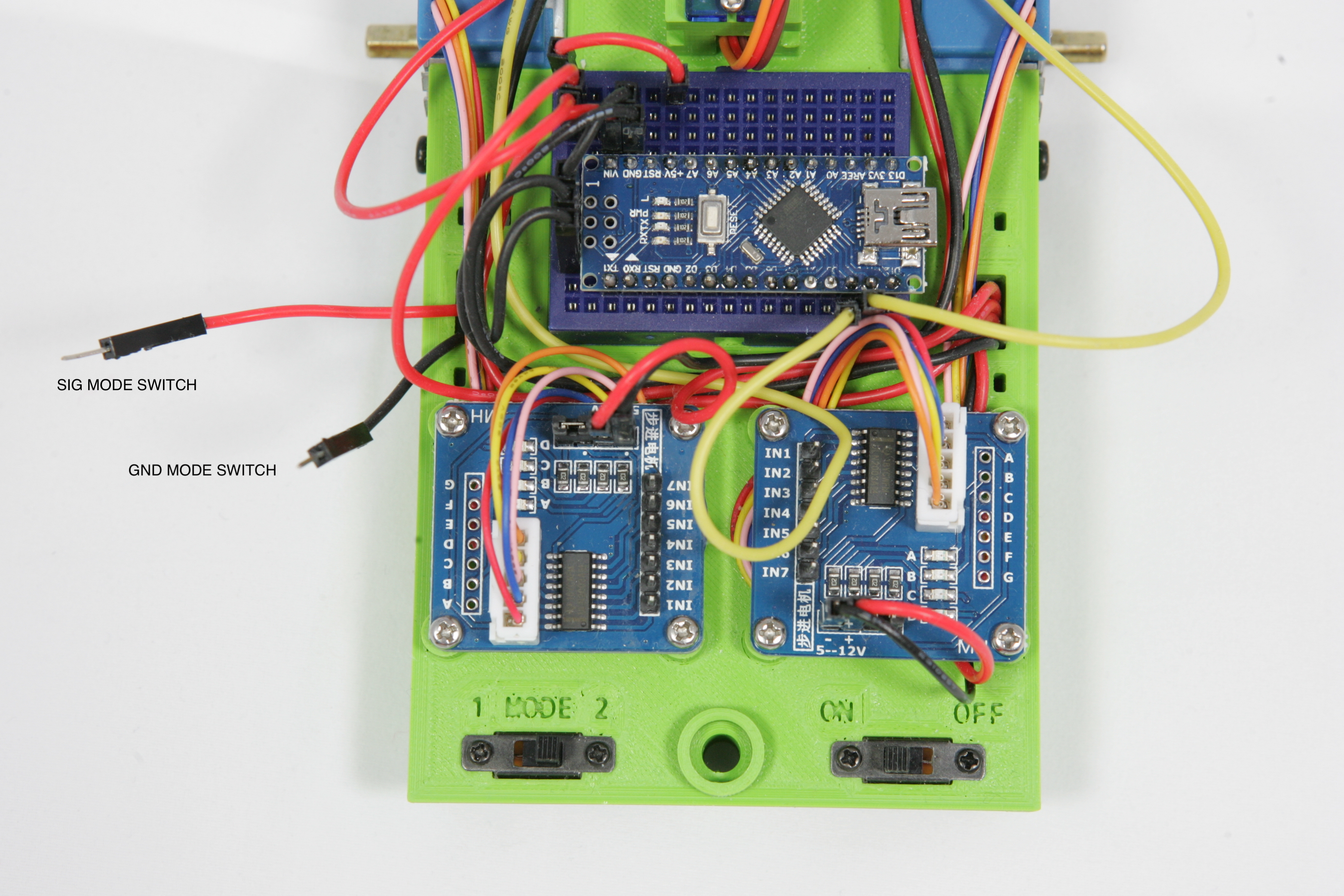
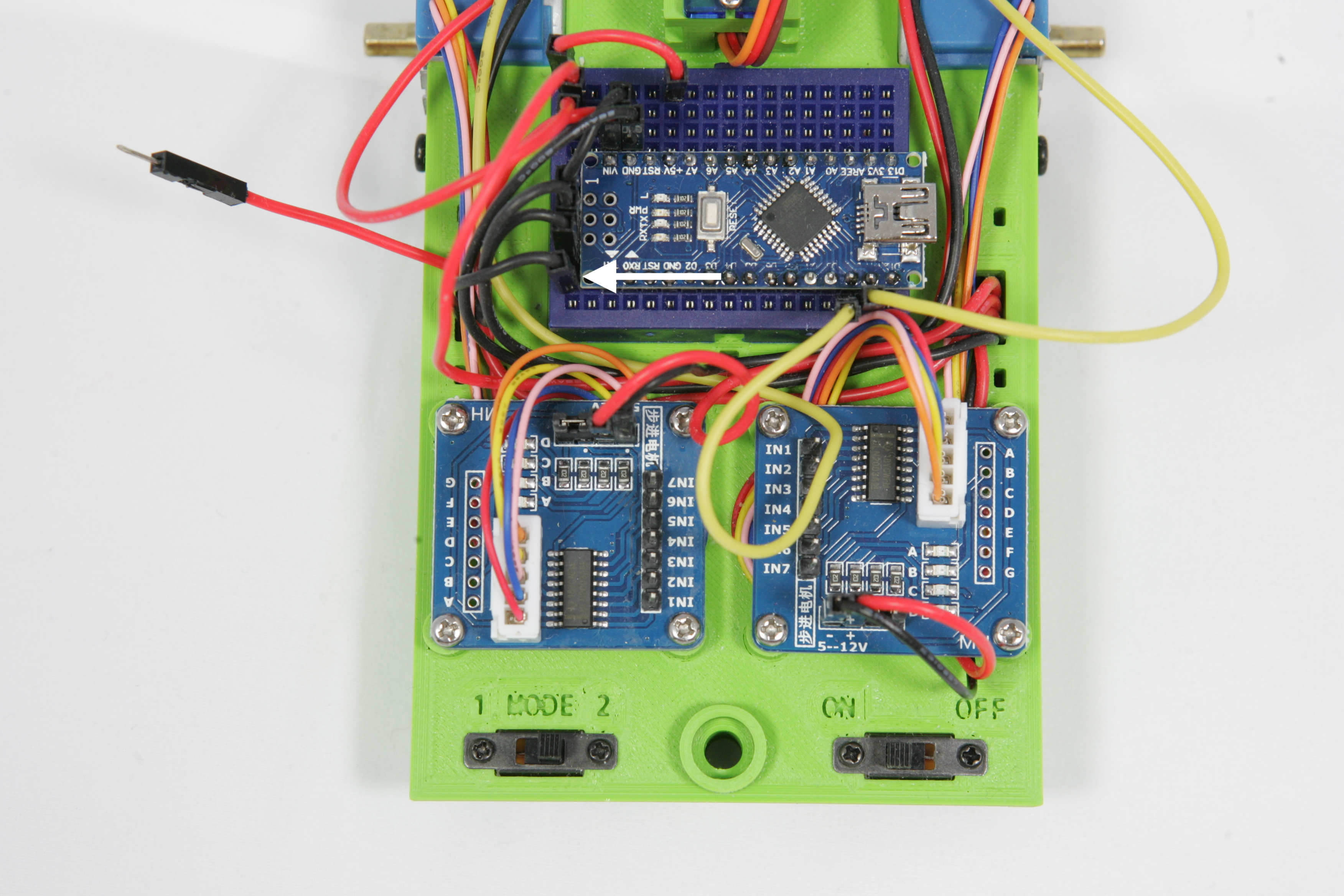
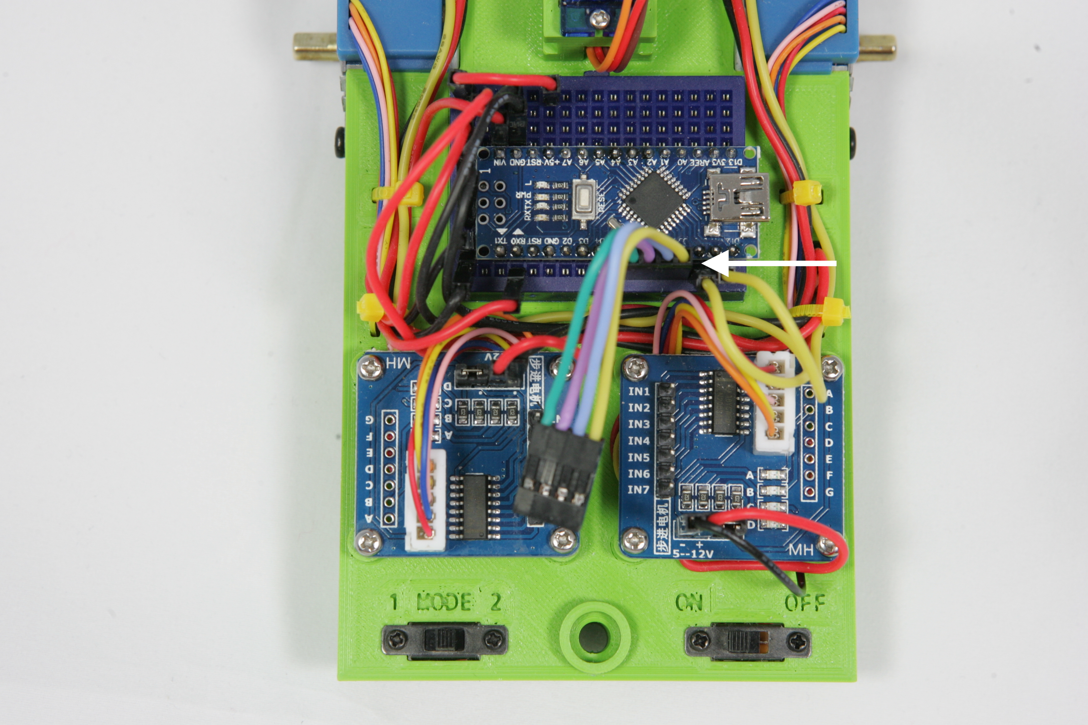
.Nearly all wires are now in place. The wires of the mode-switch still have to be connected so you can give the robot a command with this switch later on. Take the wire GND MODE SWITCH and place it in one of the last two places on the bottom left side of the breadboard. Then connect the wire SIG MODE SWITCH to connection 0 of the Arduino. Take a good look at the Nano Pinout overview where this connection is located.
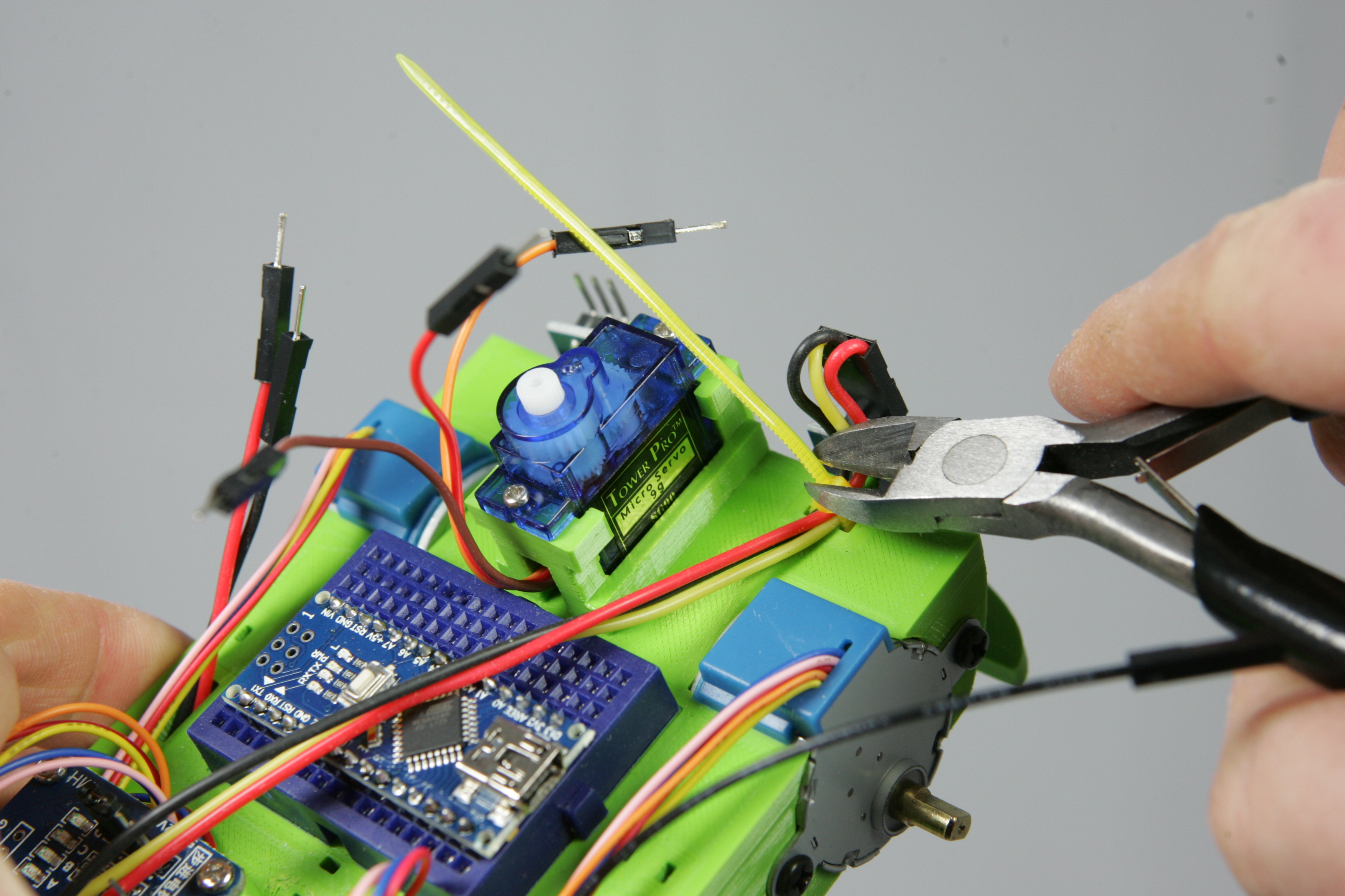
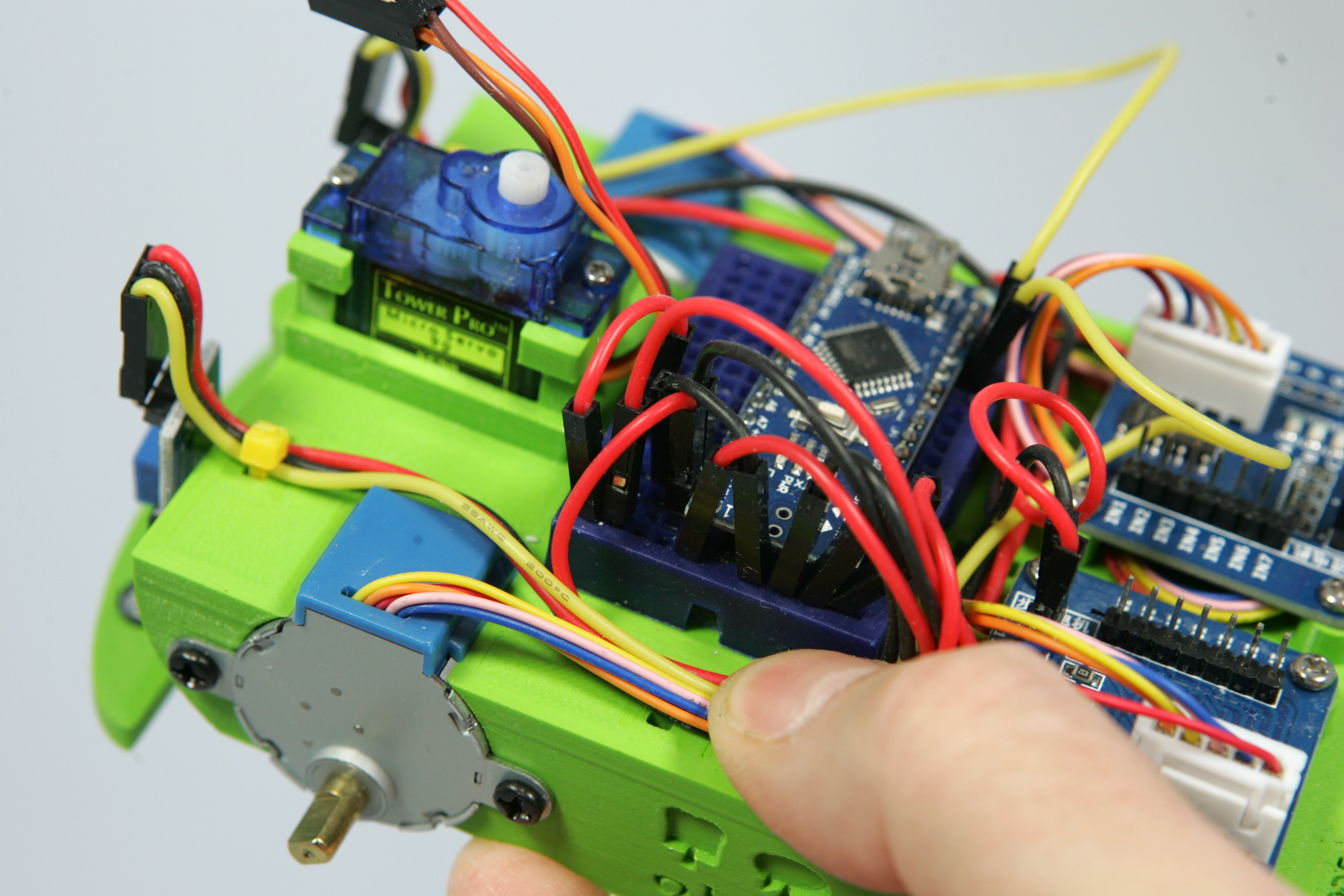
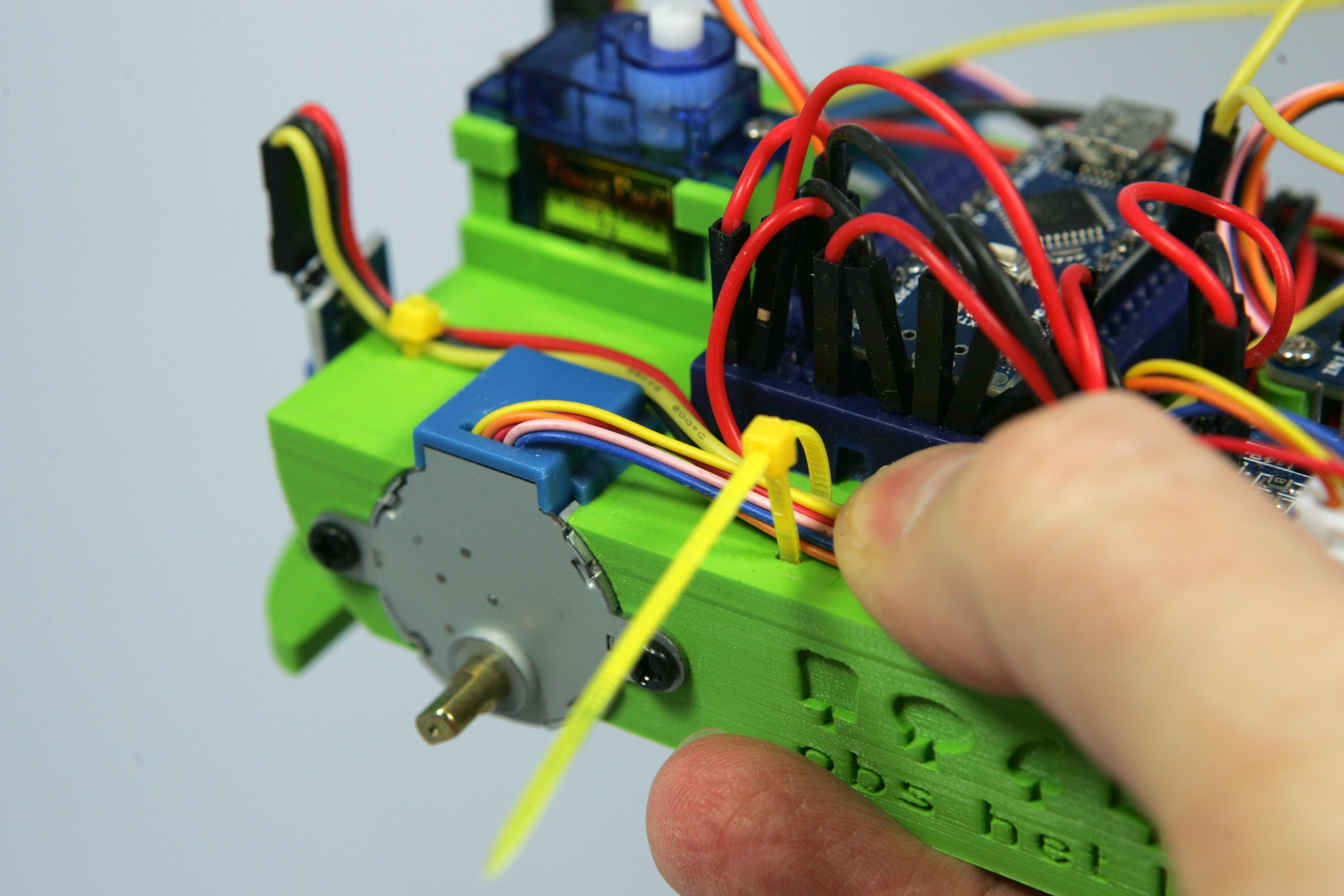
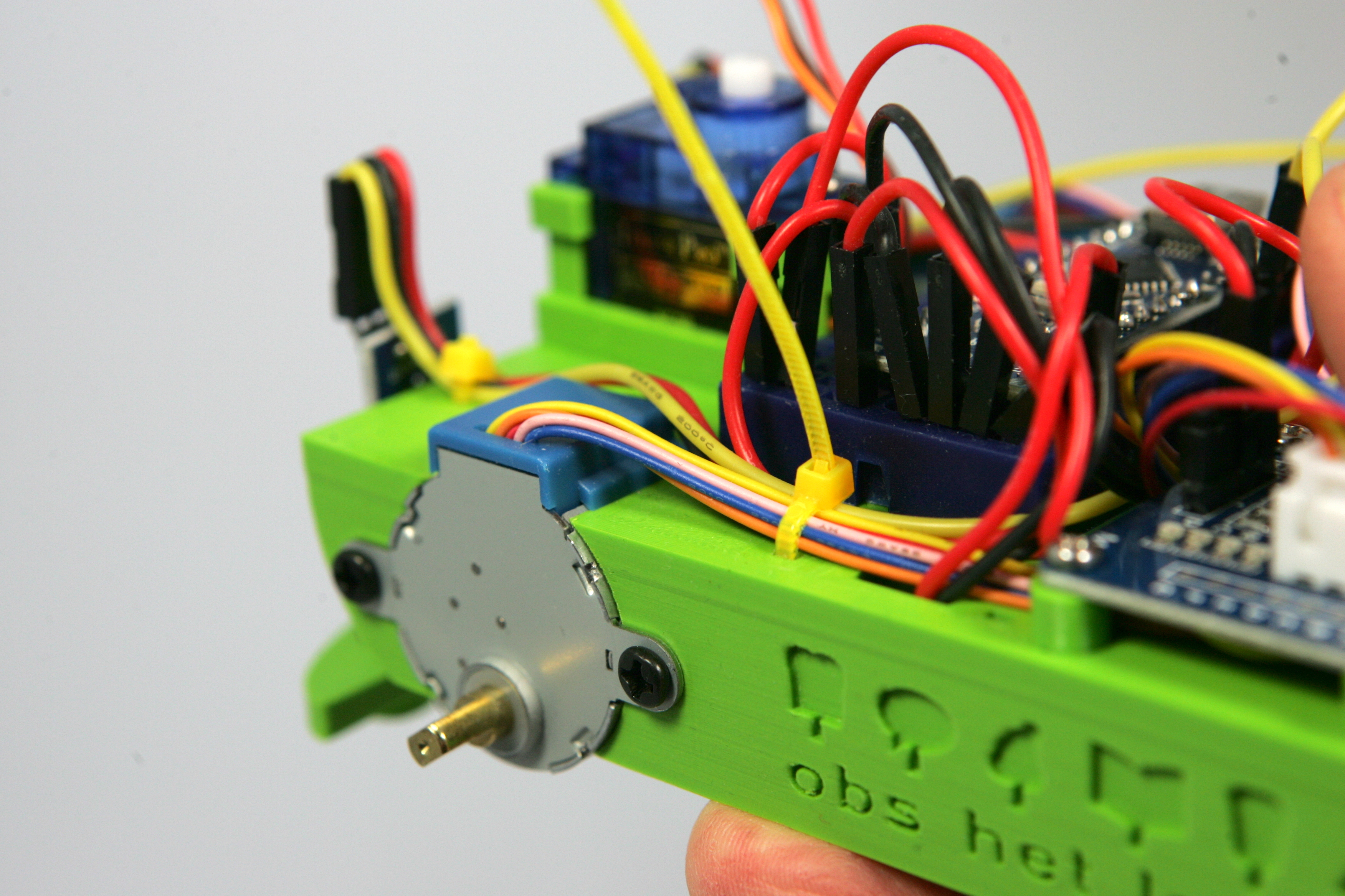
That's it! The wires are still a bit of a mess. We will solve this by securing the wires with the five remaining cable ties. Lay the wires neatly down and then loosely fasten the cable tie. Then place the wires a bit neater and tighten them by tightening the straps. Do not pull the ties too tightly, it is only the intention that the wires stay neatly in place.
There are also a number of wires at the bottom, you also need to fasten them neatly with the same cable tie. Some cable ties require you to attach wires to the top and bottom of the cable tie. With one of the five cable ties you can't just get the cable tie through the frame. How are you going to solve this?
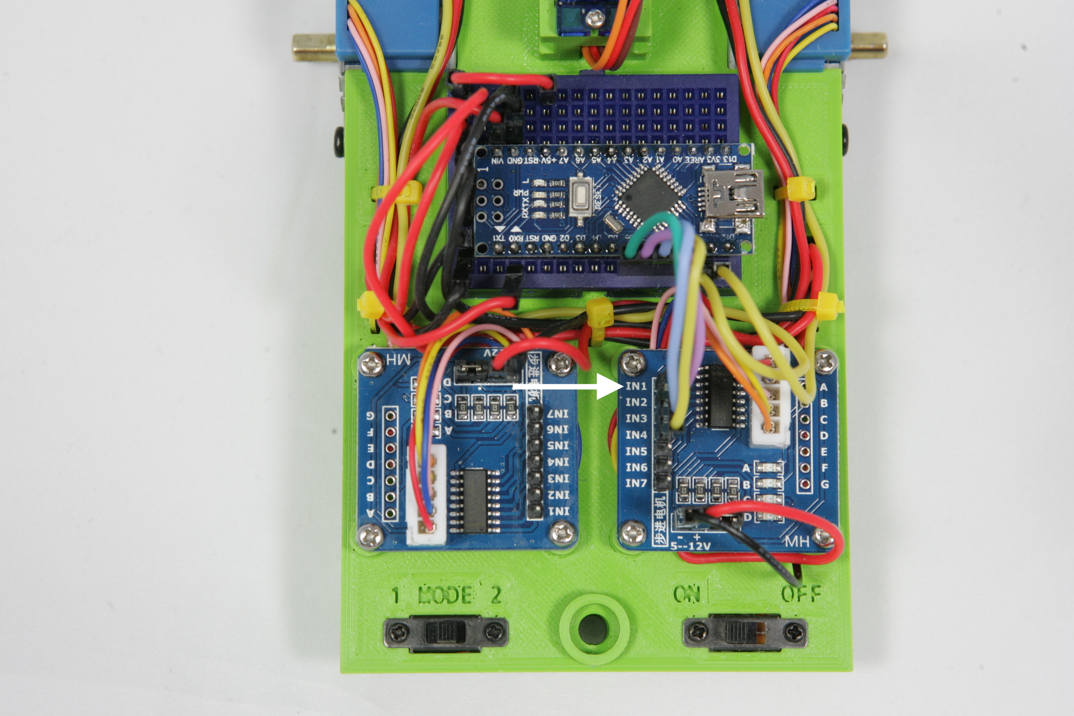
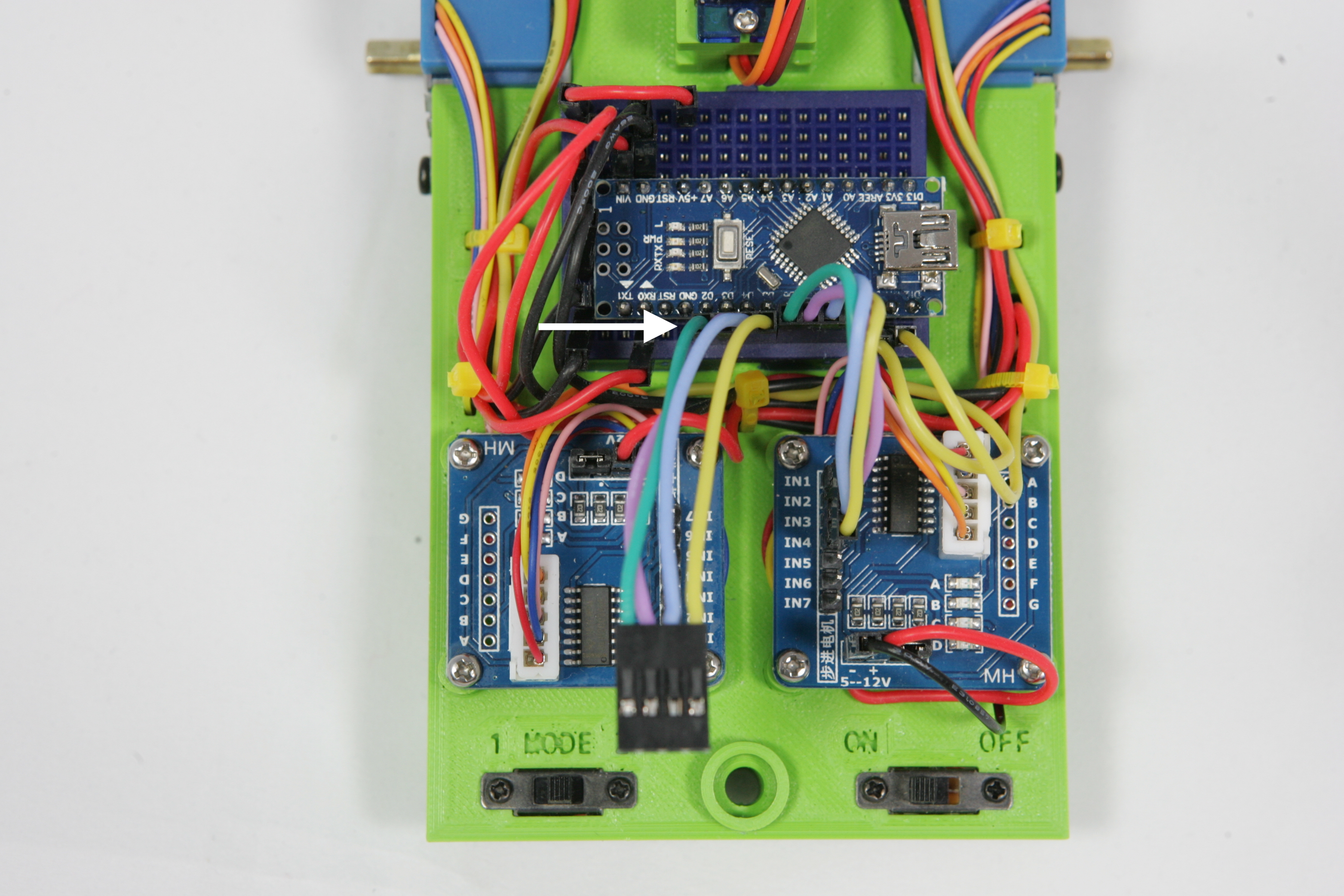
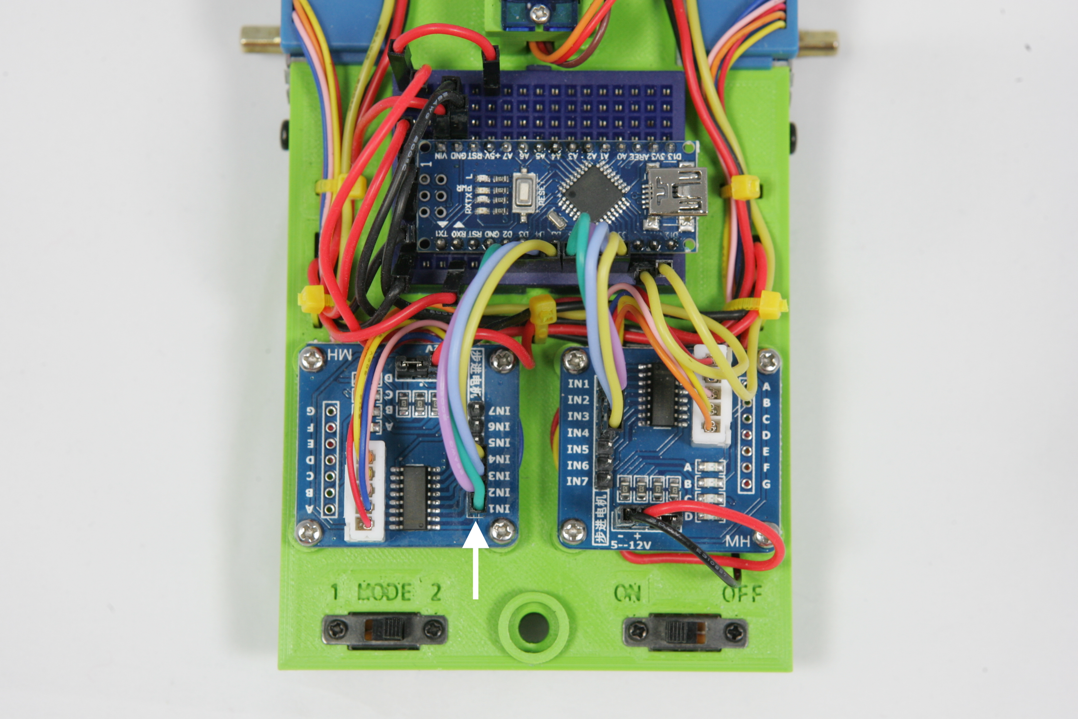
The Darlington drivers are connected to the motors, but not yet to the Arduino. Take one of the two Darling driver cables. Connect the side with the pins (male) to the Arduino. For the right motor it must be connected to connections 6 to 9. Connect the other side of the cable to the right Darlington driver. You have to connect the cable to IN1 to IN4. Attention! Connection IN1 must be connected to connection 7 on the Arduino. If you connect it incorrectly, the robot will soon drive in exactly the opposite direction to what you want.
Now you are going to do this again but for the left Darlington driver. Connect the cable to connection 2 to 5 on the Arduino. Connection IN1 must be connected to connection 3 on the Arduino.
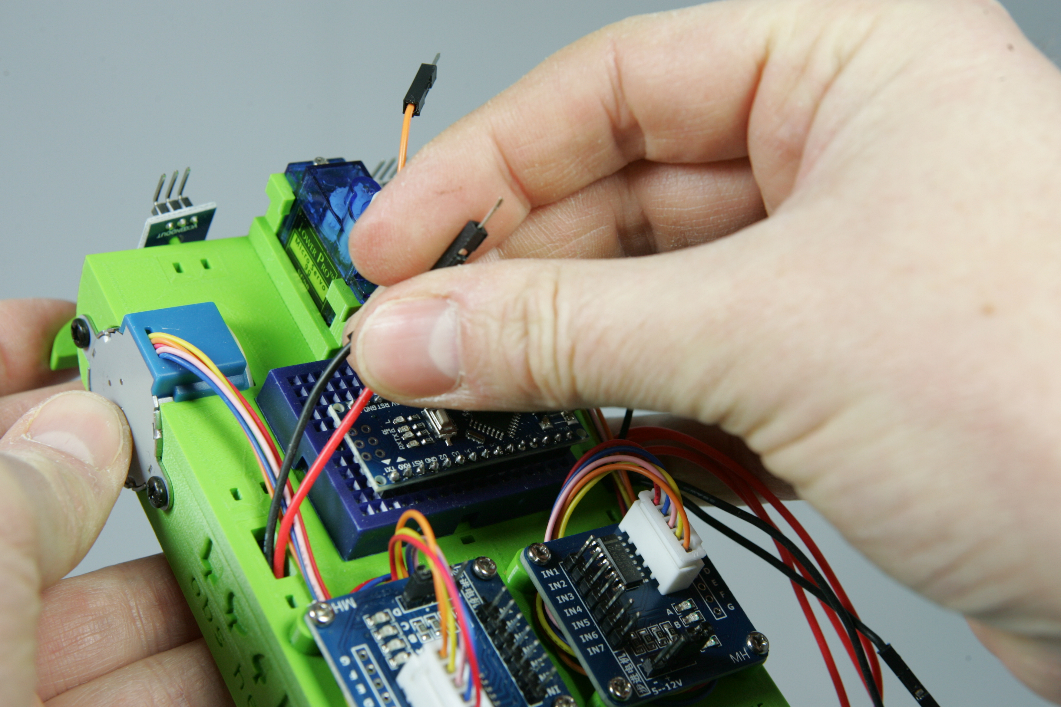
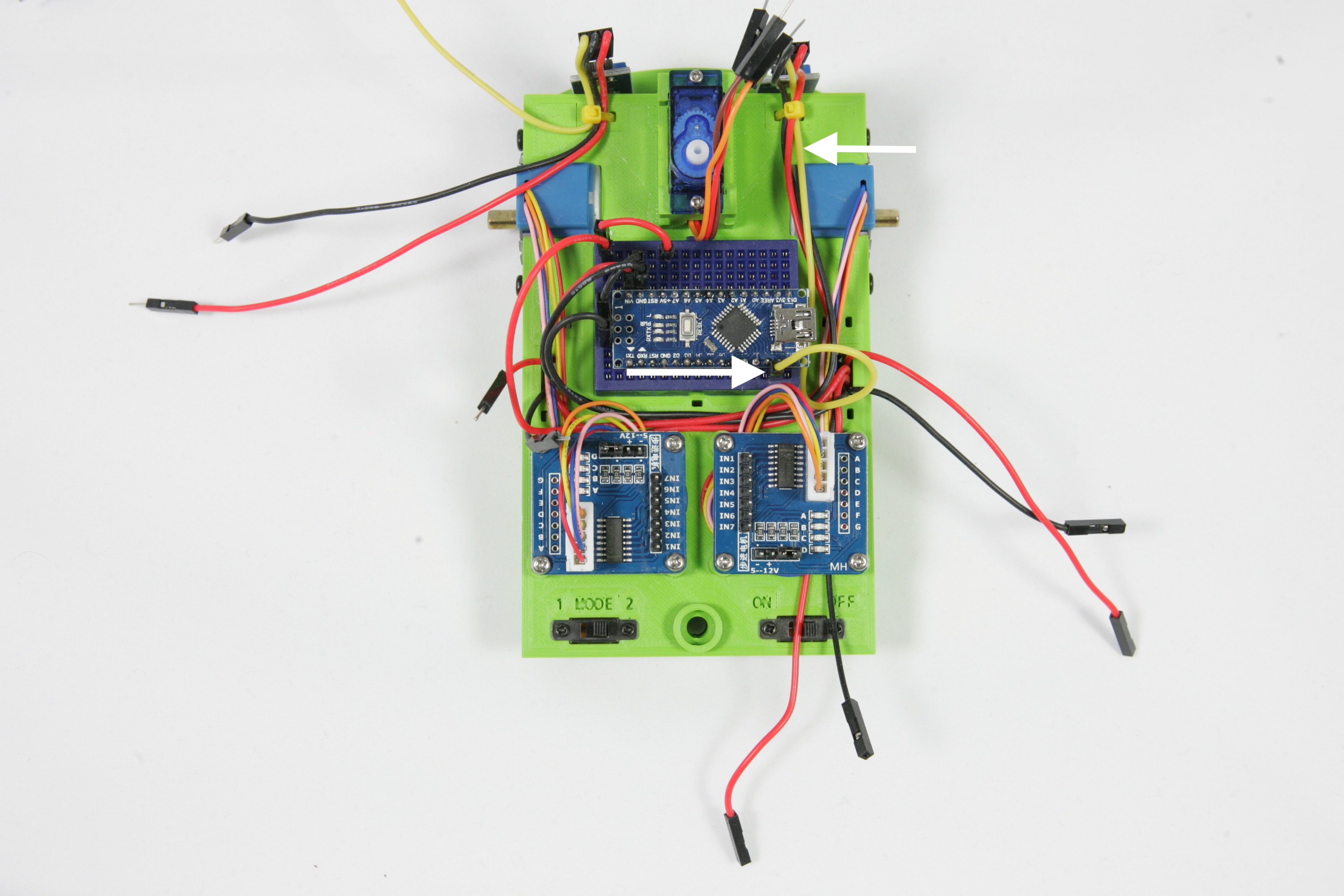
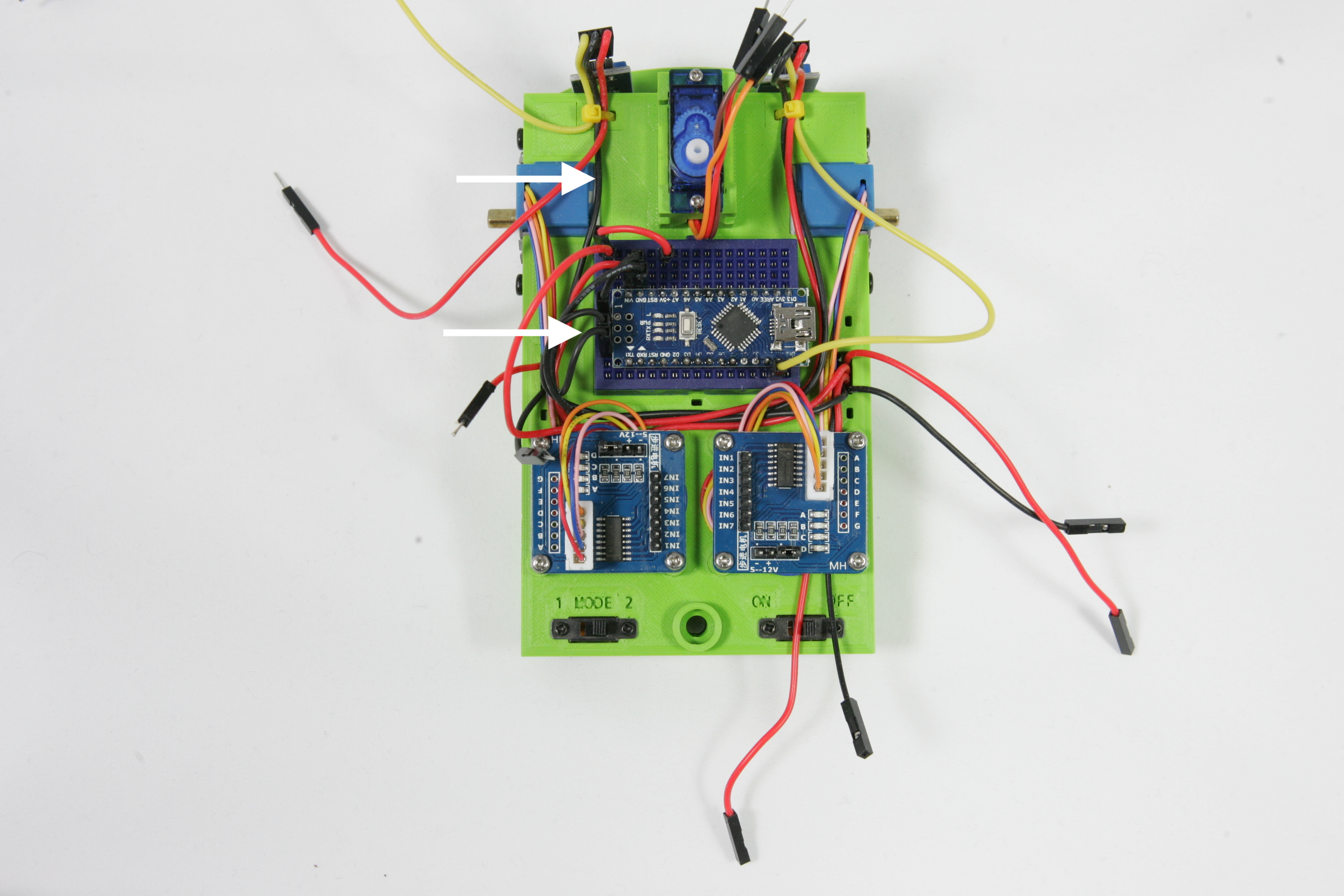
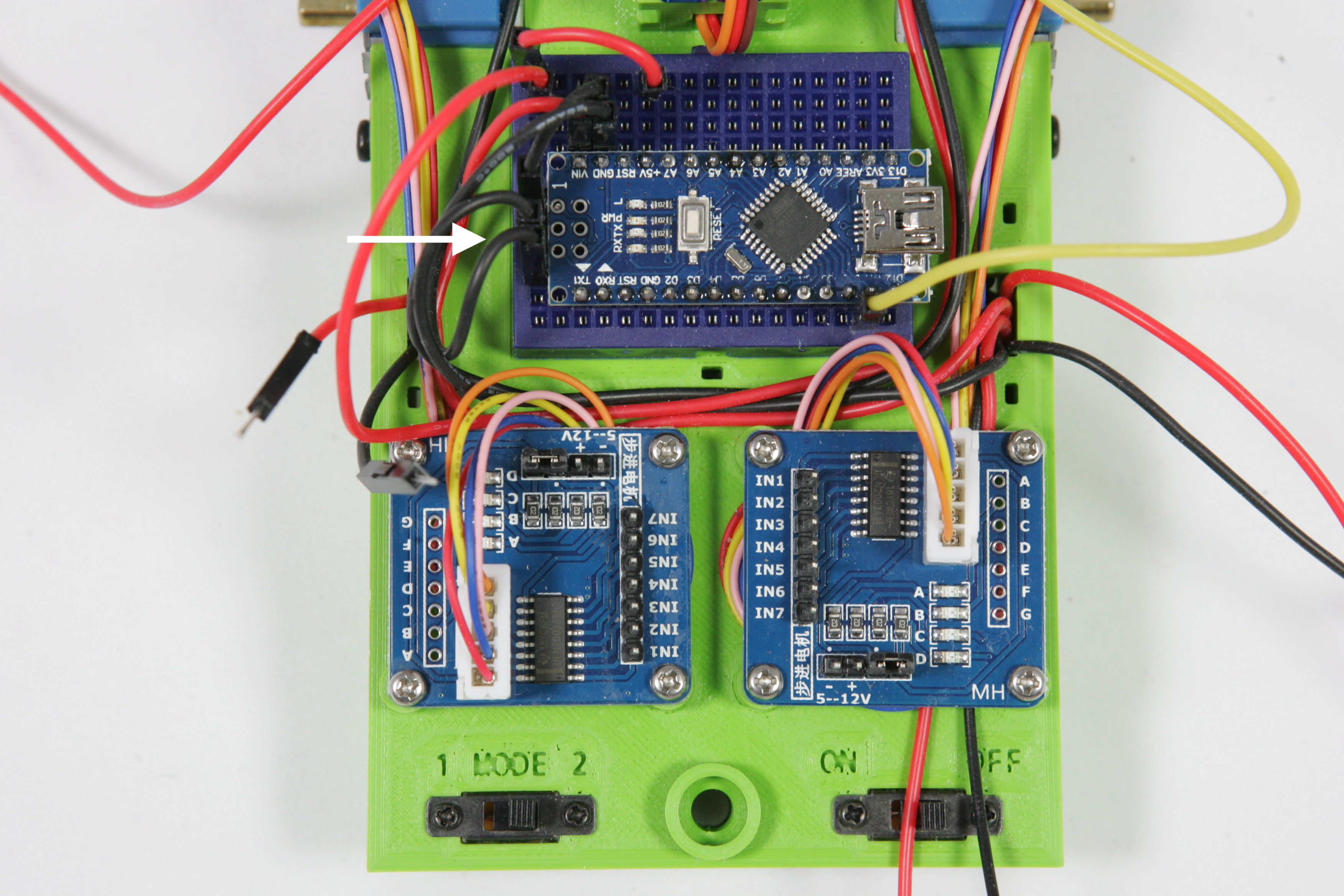
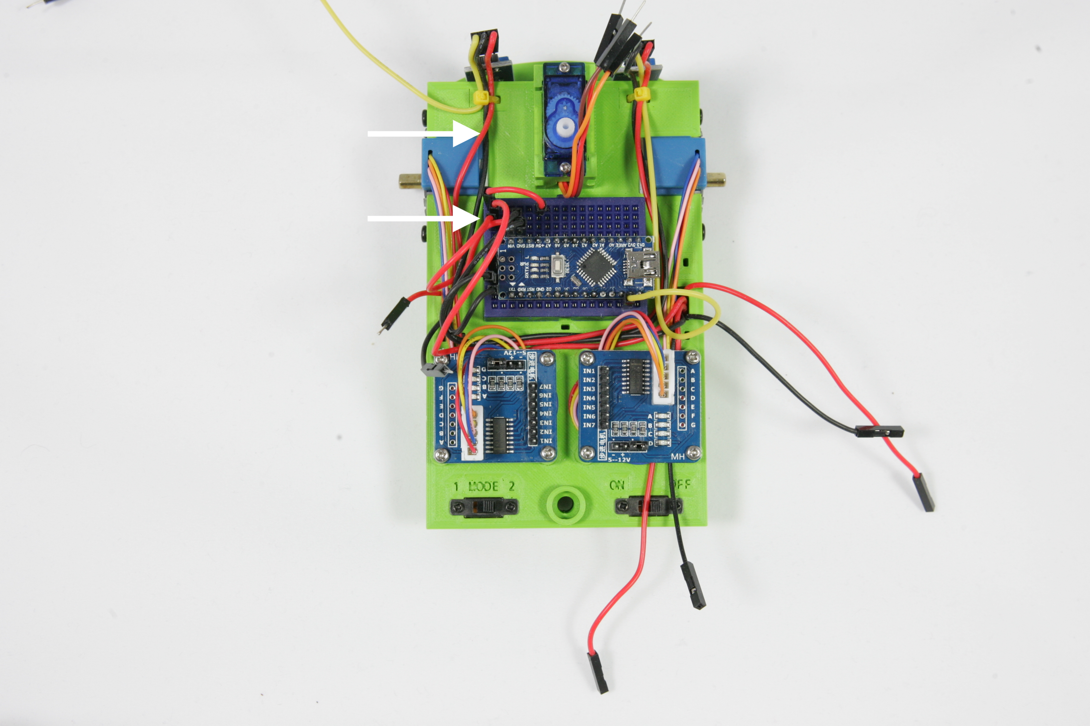
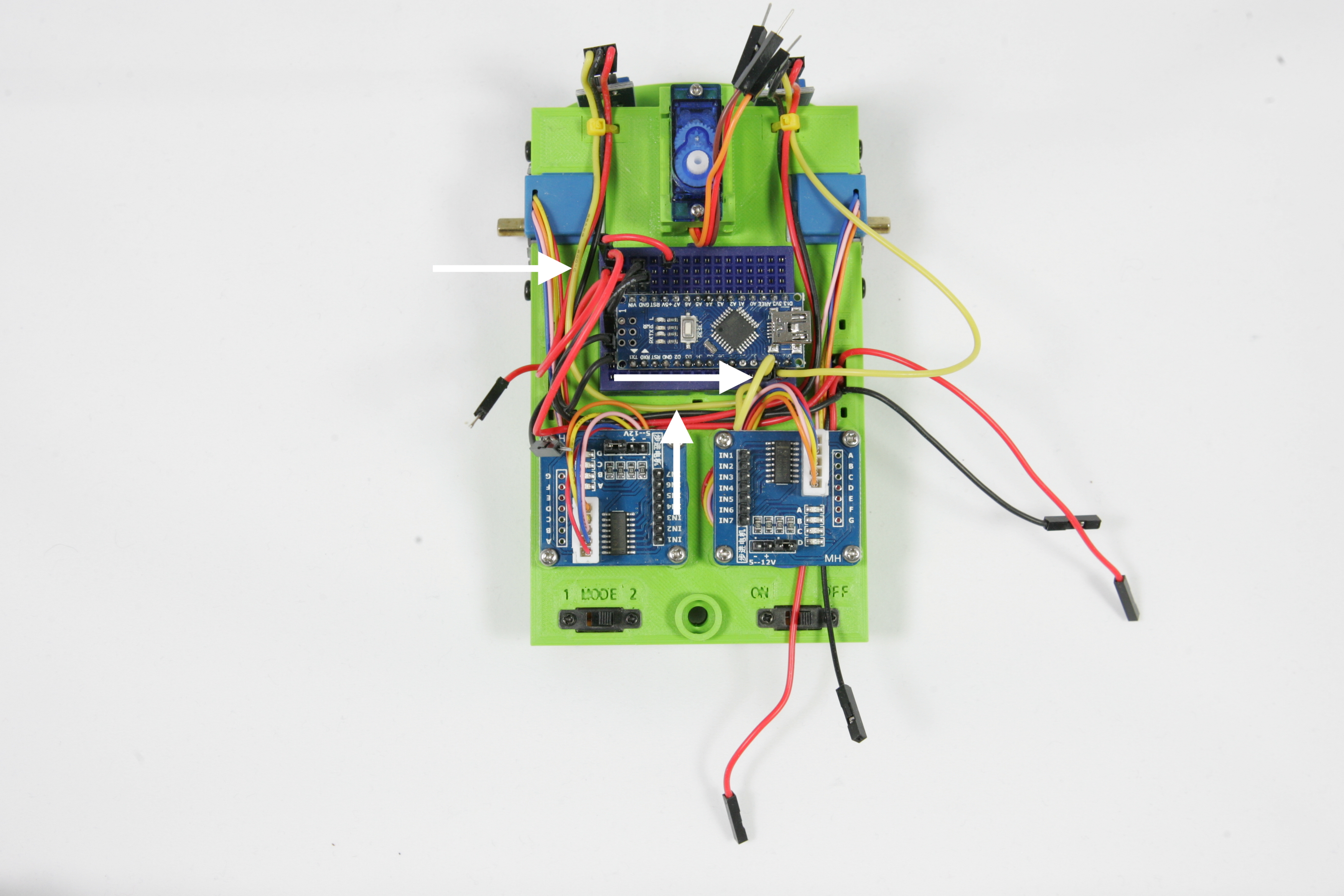
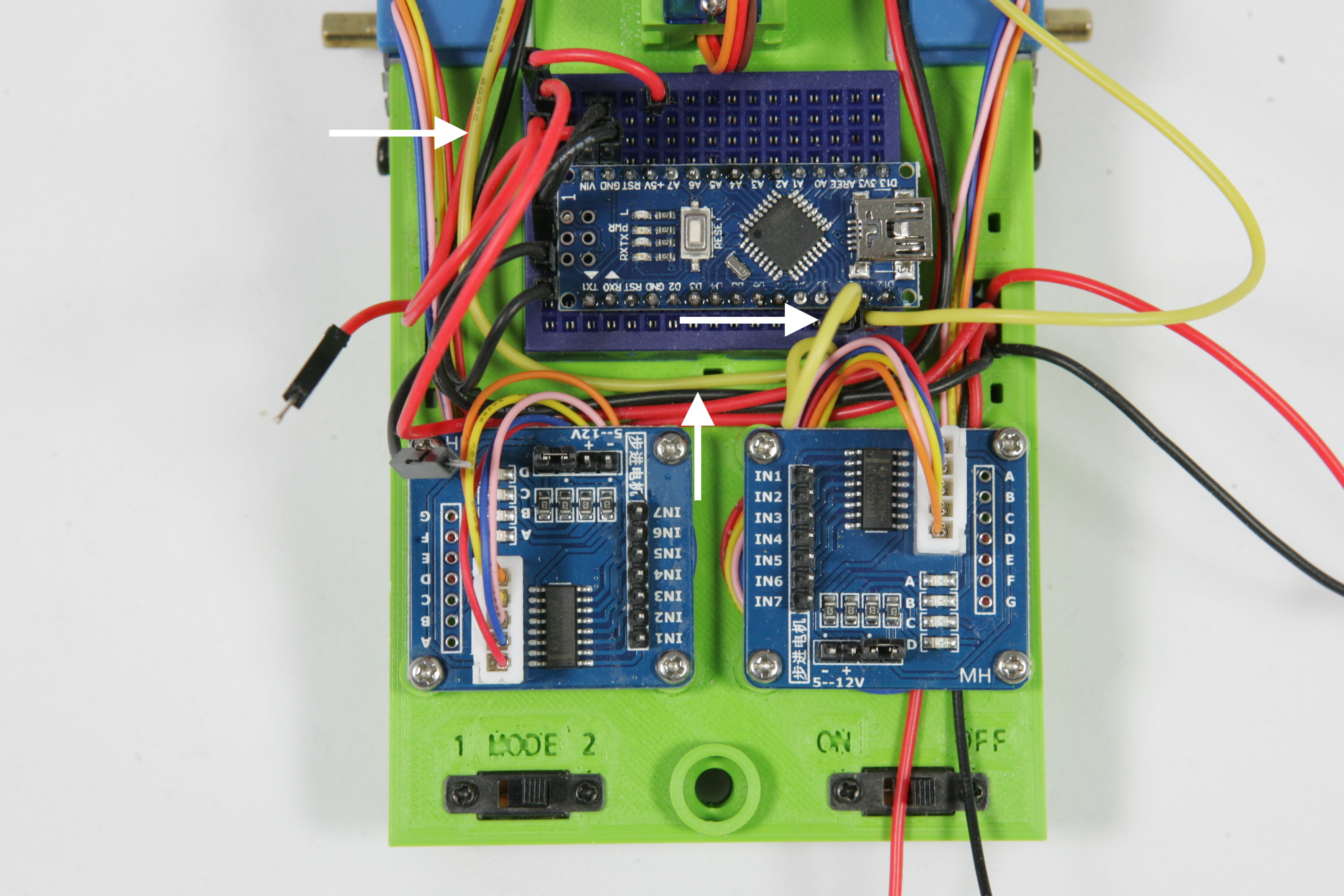
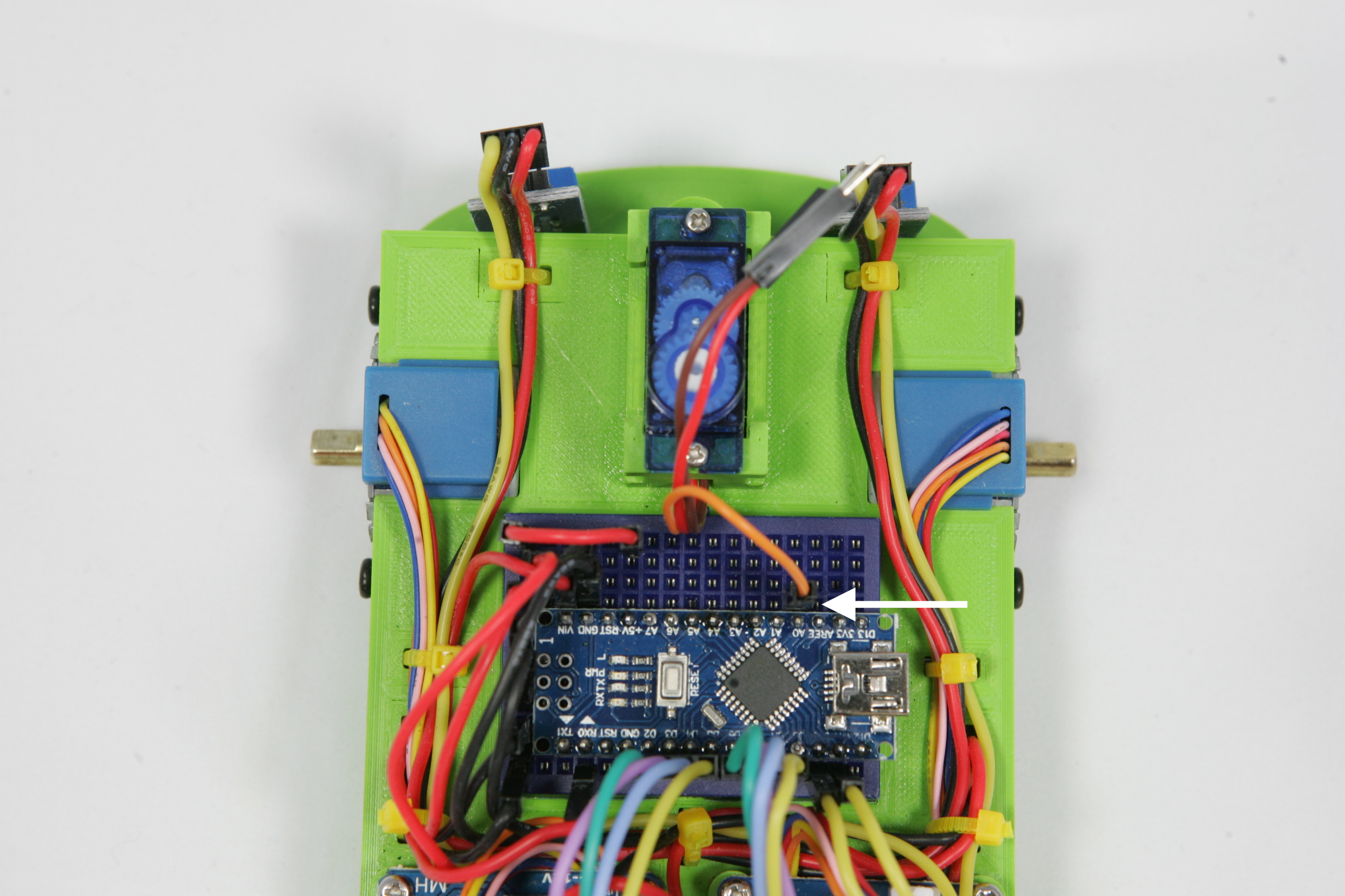
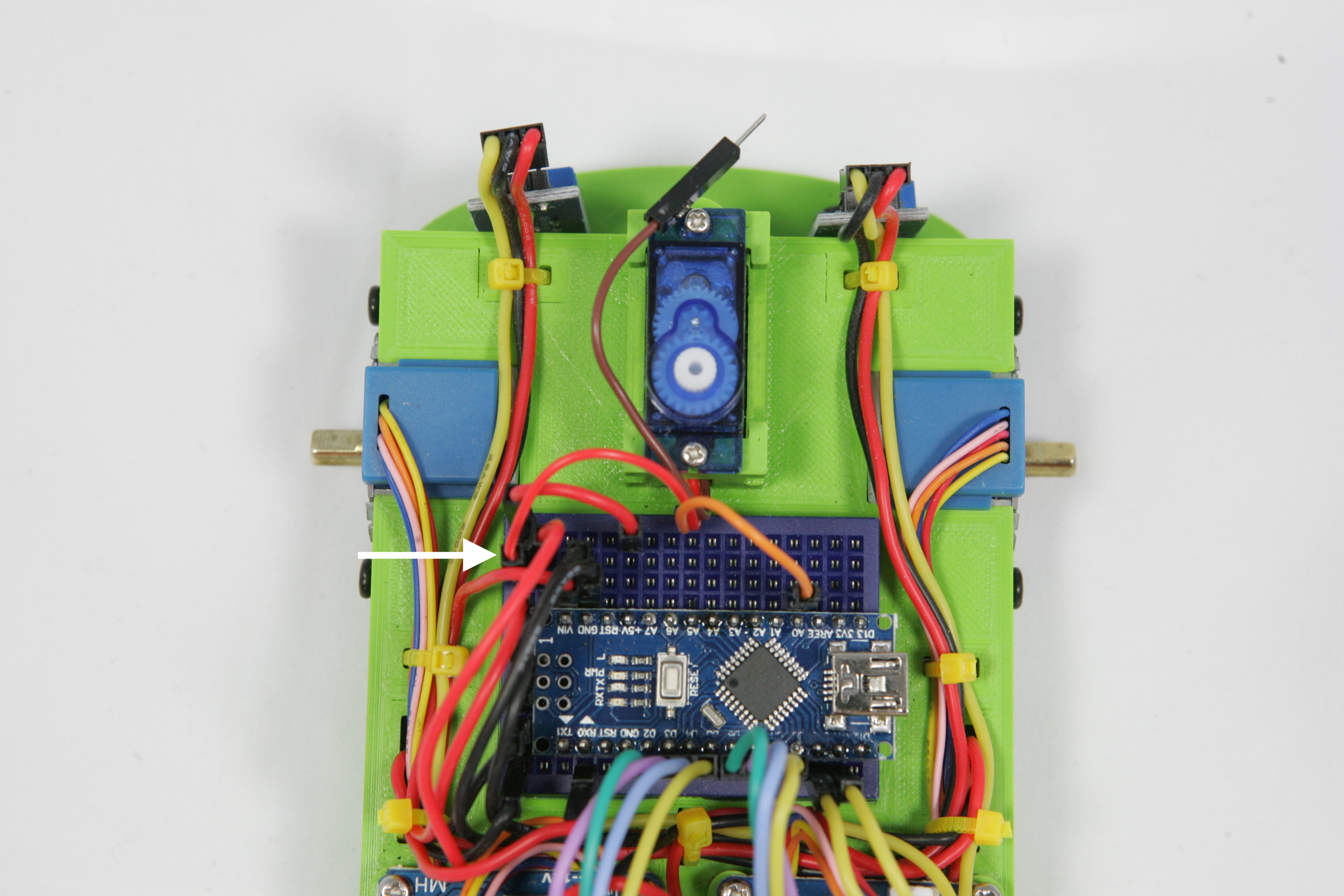
After this you will be ready connecting wires for the time being! The last three wires for now are GND SERVO, VCC SERVO and SIG SERVO. Connect the wire VCC SERVO to connection 14 of the Arduino. Connect the VCC SERVO wire to the top leftmost row of the breadboard connected to 5V
Finally, connect GND SERVO to the GND connection of the Arduino
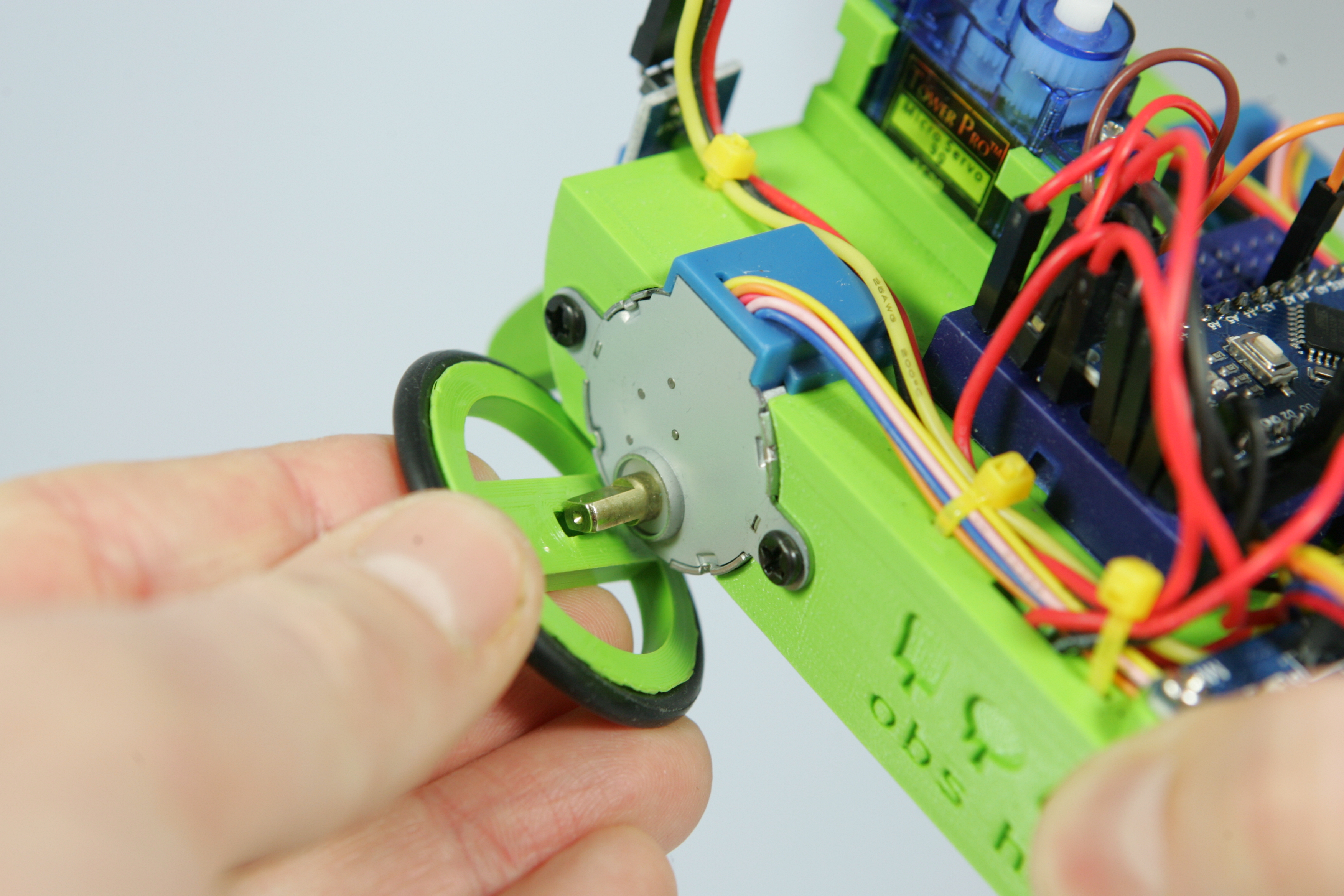
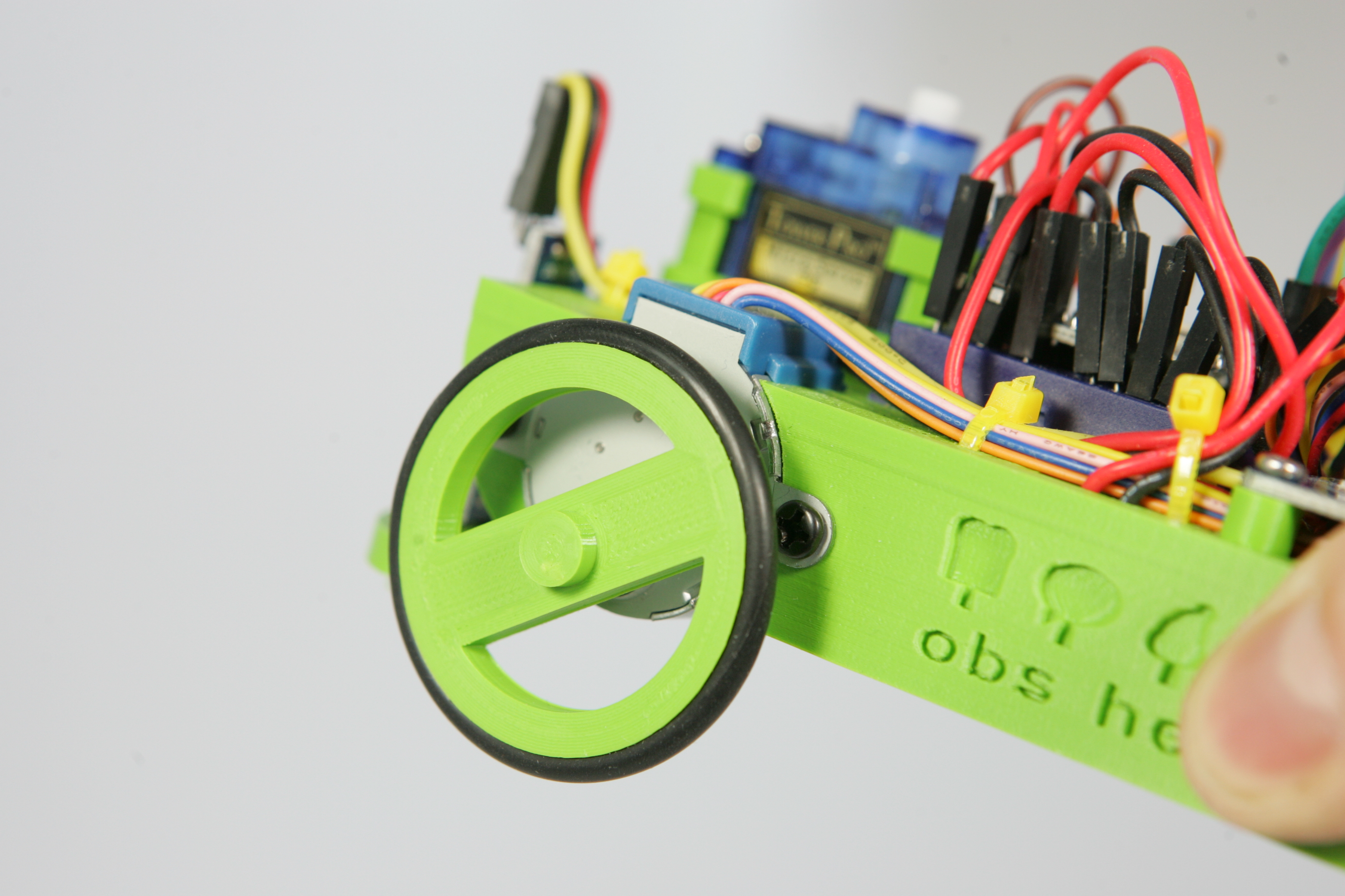
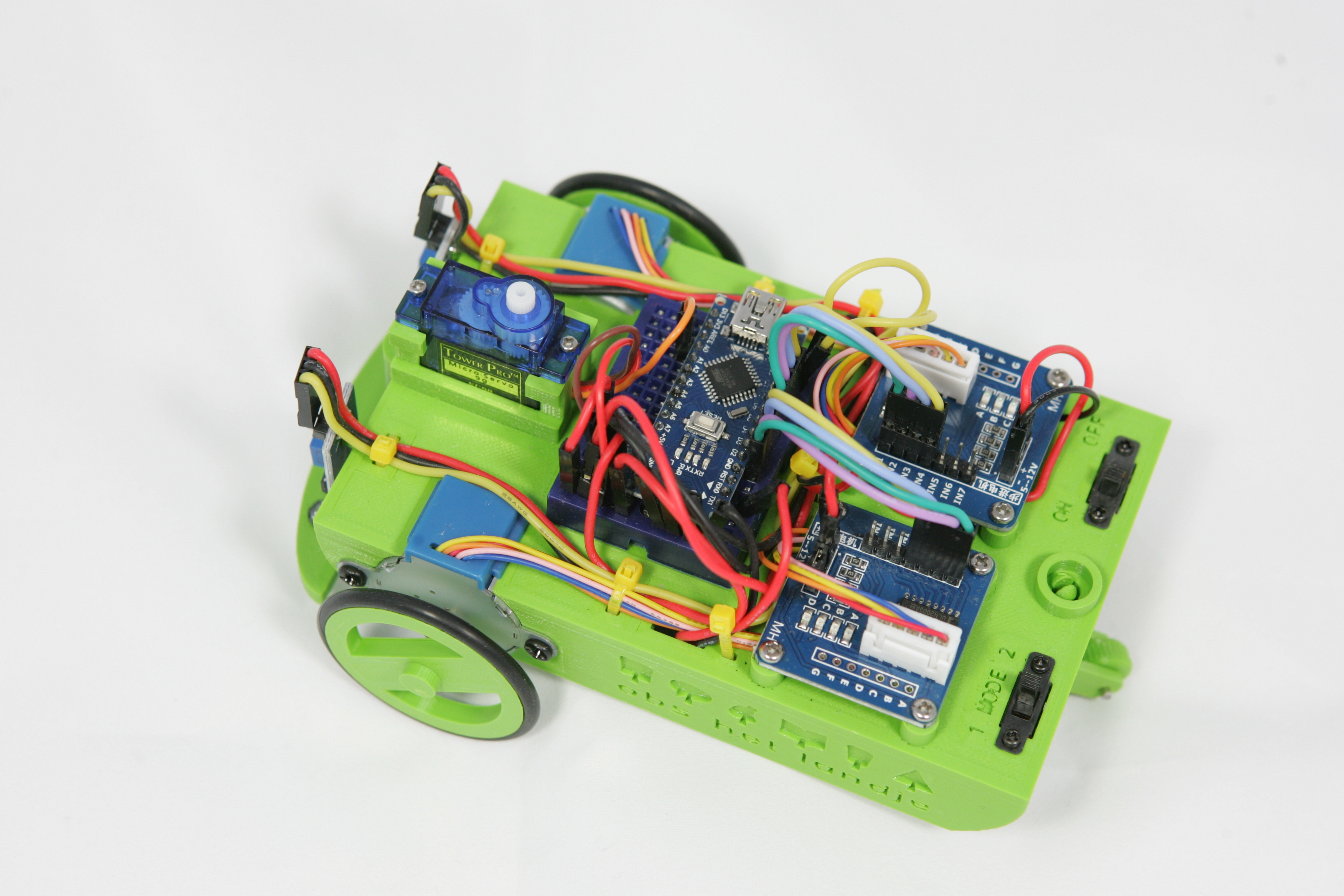
.It is already starting to look like a robot, isn't it? By setting up the wheels you make it even more complete! Put the rubber tyres on both wheels and press the wheels carefully on the axles of the motors.
Do not push the wheels straight on the axles, but start by holding the wheel a little diagonally on the axle. Look carefully how you start, the axles at the end are not round but rectangular. Make sure the wheel is right in front of the axle before you push it gently on it.
You place the rear wheel by sliding it from the bottom into the recess.
There it is, your robot! Almost finished, you will place the head of the robot later on.
Maybe you've heard of it before, variables. But what are variables actually? A variable in a program is something that can change. A variable in a program always has a type, name and a value.
It's best to compare a variable with a drawer in a cabinet. You can put something in the drawer and at a later moment see what is in the drawer. You can also take something out of the drawer or replace what is in it with something else. Variables are special drawers that are only suitable for storing one thing of one kind. If you want to store multiple things you need to program multiple drawers. To be able to indicate which drawer you mean in a program, each variable has its own name.
What kind of things you can store in a variable is indicated by a type. You also don't store your game console in a sockstand and your socks in a kitchen drawer! For now you will use three types of variables; strings, integers and booleans. What are these ?

A String is daily life is thin thread of rope. A variable of the type String is something like a rope of characters. So it doesn't matter if it's one or a lot of characters as long as they're consecutive. To indicate the beginning and end of a string, you have to put the characters between two double quotes, ". So "This is a String" is a string, and "123 :-)". also.
If you program a variable you first specify the type of the variable, then the name. By typing a "=" after the name of the variable you can specify what should be stored in the variable. After the = sign you indicate what should be stored into the variable. This is also called assigning a value. In the example below you assign the value Peter to the variable name. This variable is of the type String. With String you can tell that the type of the variable is String.
String naam = "Peter" ;Besides variables of type String you have integers. And integer is a whole number. The numbers 0,1,1,1,2,3,5,8,42,1138 are integers, the number 3,14159265359 are not. Because an integer always has a clear beginning and end, there are no double quotes at the beginning and end of the value. If you do, the computer thinks the value of the type String is.
With the word int you indicate that the variable is of type integer. This variable can therefore only contain whole numbers.
int value = 42 ;You can also assign the same value to a variable of the String type.
String value = "42" ;There is only a big difference between the two variables above. The computer can make calculations with the value variable of type int, but because the computer does not recognize the variable value of type String as a number, it cannot make calculations with the variable of type String.
So the computer can calculate 2 x 21 is.
int value = 21 * 2 ;But do not calculate what "2 x 21" is. The value of the variable value in the example below is '21 * 2'. It is a String, a thread of, the characters '21 * 2'.
String value = "21 * 2" ;The last type of variable is boolean. This variable has only two values, true and false. This type will be used a lot, not only in variables but also as a result of equations. If you compare something in a program, for example the value of two variables, the outcome is always true (true) or untrue (false).
A variable of the boolean type is defined by the word boolean. In the example below, create the trueornot variable of the type boolean and assign the value true (true).
boolean trueornot = true ;Connect the Arduino Nano of the Robot to your Chromebook with the USB cable and start a new sketch in Arduino Create. If you don't know exactly how to do that, then take a look at Lesson 1. Then write in the function setup a program in which you create three variables, assign a value to it and print the value of the variable.
The first two lines of the function setup() start with
  Serial.begin(9600);
  delay(2000);
These two lines ensure that you can see the values in the Arduino Create monitor when you print them.
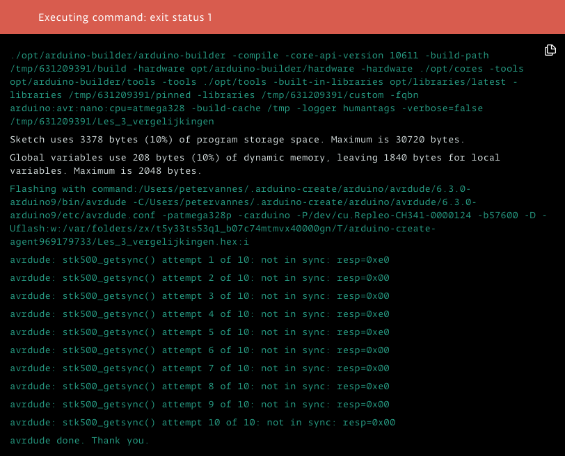
It is possible that when you upload your program to the Arduino you will see a red bar at the bottom of the screen with the text Executing command: exit status 1. Arduino create indicates with a value if the upload to the Arduino went well. If all went well the value is 0, with all other values something went wrong and a red bar appears.
Below the red bar a log is shown. A log is a list of events, things that have happened. In a log important things are kept, for example when something goes wrong.
If you get a red bar when uploading your program, look in the log what the possible cause is. This is not always easy to find or understand. If you see multiple messages which look like the message avrdude: stk500_getsync() attempt 10 or 10: not in sync: resp=0x00 then probably the mode switch on the robot is in position 2.
Set the mode switch to position 1 and then try uploading the program again.
Do you see something you don't expect with the variable trueornot? If you assign a value false 0 will be printed, when the value true is assigned a 1. This is the same for the computer, so you can also enter 0 instead of false and 1 instead of true.
The content of a variable can be compared with a value or another variable. The result of a comparison is always true or false, so true or false.
If you want to compare the contents of two variables to test if they are equal, then you indicate this with "==". Each side of the "==" must have a variable. So the example below prints "1" because the contents of var1 and var2 are the same.
String var1 = "abcd" ;
String var2 = "abcd" ;

Serial.println(var1 == var2);
Now write a program "Lesson_4_equations" that creates three variables, var1, var2 and var3. The variables var1 and var2 are given the same value. Assign a different value to variable var3.
Now print the result of the equation of variable var1 and var2. Also print the result of the equation of var1 with var3. Test your program. The result of the first equation must be true (1) and the result of the second equation false (0)
.In addition to the values of two variables, you can also compare the value of one variable with another value not contained in a variable. The result of the two equations below is the same. In the first equation you compare the content of var1 with var2. In the second equation, compare the content of var1 with the value "abcd".
String var1 = "abcd" ;
String var2 = "abcd" ;

Serial.println(var1 == var2);
Serial.println(var1 == "abcd");
The result of a comparison gives a boolean value. This value can also be stored in another variable.
Continue now with the program you created in task 4.1. Create an extra variable called outcome. In this variable you are going to save the result of an equation. Think carefully which type you use for this variable!
If you have created a variable you must assign the value of the equation of var1 and var2 to the variable output. Then print the value of the variable outcome.
.You can only compare two variables of the same type. So it is not possible to compare a variable of type String with another variable of type int. If you try to run the program below you will get the error message "error: no match for 'operator==' (operand types are 'int' and 'String')".
int var4 = 12 ;
String var5 = "12" ;

Serial.println(var4 == var5);In addition to comparing whether values are equal to each other, you can make more comparisons. You can compare whether one value is larger or smaller than another value. When comparing whether two values are equal, use "==", to compare whether a value is greater than another value, use the ">".
character.The equation gives true (is true) if the number to the left of > is greater than the number to the right. You can remember this more easily by the following memory aid : Left of the > sign is the distance between the lines large, right of the sign is the distance small. The sign can also be seen as an arrow pointing from large to small. If the values match the distance between the lines, the result is true
.In the following program example, the value 7 is shown on the left, the value 3 is shown straight. The arrow points from the largest to the smallest number. The result of this equation is true (1). The content of variable var1 is thus larger than the content of variable var2
.int var1 = 7 ;
int var2 = 3 ;
Serial.println(var1 > var2);Besides a larger than comparison there is also a less than comparison. To do this, use the arrow pointing in the other direction to "<". If in the same program you replace the larger than (>) equation with a less than (<) then the result is false (0). Because, 7 is not less than 3
int var1 = 7 ;
int var2 = 3 ;

Serial.println(var1 < var2);Create a new program Lesson_4_largersmaller. In this program, create two variables of the type int. Choose the names of the variables, for example large and small. Make the program compare the variables using the the larger than and less than comparators and show the result on the monitor.
.Try to run the program and see if the results of the equations are correct.
Besides comparing whole numbers with > and <, you can also compare String values. However, this is less obvious. Which word is larger "app" or "apartment"? It is "app" !
It is strange, or not ? The word "app" is shorter than "apartment", but when comparing string values, the equation starts with the first character. If this character is equal, the equation continues at the next character. The first two characters of "app" and "apartment" are equal. The third character compares "p" with "a". The letter "a" occurs earlier in the alphabet and therefore is smaller, just like comparing values where 0 is smaller than 5. When comparing strings, a comparison is made per character from left to right. As soon as there is a difference between the characters, the following characters no longer apply in the equation.
Below some more examples of comparisons that are true.
app > apartment
primary school landje > landje primary school
A > 1
1 < a
a4 > a3
You can see that comparing string values is not always very easy to understand. In the further exercises we will not use this kind of comparisons.
You have already learned how to compare whether values are equal, smaller or larger than another value. These equations can also be combined with each other. You can not only compare whether a value is greater than another value, but also greater than or equal to another value. The comparison 4 > 3 is true, but 4 > 4 is not. Suppose you want to compare a value that is greater than or equal to 4. Then you can do this very easily by combining the comparison symbols, for example >=. The result of the equation 4 >= 4 is then true and 4 >= 3 is also true!
In addition to the equation greater or equal , >= there is also the equation smaller or equal, <=. Just as with the larger or equal equation, with the smaller or equal equation, both 3 <= 4 and 4 <= 4 where.
Add to the program created in the previous command Lesson_4_largersmaller comparisons using the Less than or equal and greater than or equal equations.
The last equation is not equal to, !=. The result of this equation is true if both equations are not equal, so 3 != 7 is true. The exclamation mark for the = sign in the equation means not (NOT) , so it actually says "not equal".
Add to the program Lesson_4_largersmaller an equation using the not equal to operator.
You will probably think, nice these comparisons, but what can you actually use those for ? Well you can use them in conditional statements ?! Conditional what ? A statement is another word for a programming instruction, a condition is something that must exist before something else can happen . It becomes a bit clearer with the following example.
Say that you agree with your friend that you will give him a candy cane if he has helped you with your homework. Then the condition, is that he helped you with your homework. The instruction then is that you give him a candy cane. If you write this down so that it can be understood by a computer, it looks like this.
if (help me with homework) {
  Give my friend a candy cane
}
You start for a computer with if to indicate that you set a condition that must be met. This condition is between the round brackets and the outcome may only be true or false. The outcome of a condition is therefore a Boolean value. After the condition you place the statements, instructions, that have to be executed if the outcome of the condition, defined between the round brackets, is true. The following example program says if it is true, then show "The condition is true".
if (true) {
  Serial.println("The condition is true") ;
}
The boolean value true is true, so if you run the program the text "The condition is true" is shown.
Create a new program, Lesson_5_condition_if. In the setup() function, create two new variables, large and small of the int type. Fill this variable with a number. The number in variable small must be smaller than in the variable large. Then write an if instruction which prints the text "small is smaller than large" if the value in variable small is smaller than the value in variable large.
If all goes well the program of Task 5.1 now prints the text "small is smaller than large". But what if the value of small is not smaller than large? So if the outcome condition is false. Then nothing will be printed now! With an if-instruction you can also execute instructions if the outcome of the condition is not true (false). This is done with the word else. You use the word else after the instructions between { and } that is executed if the outcome of the condition is true. After else, use the { and } again to indicate which instructions you want to execute if the outcome of the condition is untrue. Just look at the example below.
if (true) {
  Serial.println("The condition is true") ;
} else {
  Serial.println("The condition is false") ;
}Customize the program now Lesson_5_condition_if. Make sure that the text "small is larger than large" is printed if the value in variable small is larger than the value in variable large. Also adjust the value of one of the variables so that the new text is printed.
Repeatative work is boring! But sometimes useful. Just think about learning the tables. If a computer has to repeat a certain job every time you want to, you can program this more times, for example if you want to print 5x "I repeat this", you can write it like this.
Serial.println("I repeat this") ;
Serial.println("I repeat this") ;
Serial.println("I repeat this") ;
Serial.println("I repeat this") ;
Serial.println("I repeat this") ;
For a few repetitions this is still clear, but suppose you have to repeat something a thousand times. Then the program becomes very long and still does not do much. To make this easier and more convenient there are loop, instructions. Of these, we'll discuss two, the for and the while loop.
While means as long as. The instruction while works similarly to the instruction if. If you start with the name of the instruction, while, a condition will appear between two round brackets and instructions between { and }. These last two characters are also called braces.
while (true) {
  Serial.println("I repeat this") ;
}
The while instruction repeats the instructions between the braces as long as the outcome of the condition is true.
while loop repeats printing the text?If you want a while loop to stop repeating at some point, you must make sure that the condition changes from true to false during the repeat. If you don't make sure the outcome of the condition changes, the repeat will never stop.
Check the example below and try to understand when the while condition changes.
int number = 1 ;

while (number < 10) {
  Serial.println("I repeat this") ;
  number = number + 1;
}
The program starts by creating a variable number and assigns it the value "1". The condition number <= 10 in the while-loop then is true. The text "I repeat this" will then be printed. Then the instruction number = number + 1 is executed. The variable number will get a new value here. This new value is the current value in variable number, "1", plus 1. The new content of variable number becomes 2. The result of the while-loop condition is still true, so the instructions between { and } will be repeated again.
Try now to find out how often the text "I repeat this" is printed by the previous example program. Do this by going step-by-step through the program rules and writing down the contents of the variable number and when something is printed.
Write down for example;
number 1
"I repeat this"
number 2
"I repeat this"
The for-loop also allows you to repeat multiple instructions. Instead of just a condition, you have to place a initialization, condition and increment between the round brackets in a for-loop. But what are initialization, condition and increment?
Initialization means creating again, it is creating a variable and assigning an initial value. The instruction int number=1 for the while-loop example program showb below is the initialization of the variable number
You have already dealed with a condition before, this is for example number < 10 shown in the while-loop example program below.
Increment is another word for addition. With this you indicate how much the value of a variable will be increased. In the while-loop example program this is executed in the loop by the instruction number = number + 1.
The initialization, condition and increment in a for-loop must appear in parentheses after the instruction for. Between the initialization, condition and increment type a semicolon (;). So it looks like this
for (initialization;condition;increment) {
  // Instructions
}
If we want to do exactly the same with a for-loop as in the "I repeat this" while-loop program, the program looks like this.
for (int number=1;number<10;number=number+1) {
  Serial.println("I repeat this") ;
}
In a for-loop you actually put all instructions which ensure a good progression of the repetition together. The variable is initialized, number gets the value 1. Each repetition a value of 1 is added to the value of the variable number. And the instructions are repeated as long as the value of the variable number is less than 10.
If you want to increase the content of a variable by exactly 1, you can also write it down differently. By typing "++" after the name of a variable, for example number+++, this is the same as number = number + 1, so the previous program does exactly the same as the program below.
for (int number=1;number<10;number++) {
  Serial.println("I repeat this") ;
}
This will be a more difficult task, so take your time and think carefully. Write a program that calculates the power of a number. If you want to calculate 2 to the power 4, you calculate the outcome of 2x2x2x2. Two times two is four, four times two is eight and eight times two is sixteen. Two to the power 4 therefore is 16. To calculate a power of a number you need a ground number and a exponent. The base number is the number you want to multiply, the exponent is the number of times you want to multiply the number.
Start the program by creating three variables, ground, exponent and result. Decide for yourself which type of variable you use. Make the content of the variable result equal to the value of ground and choose your own value for the variables ground and exponent. Start with small numbers to keep it comprehensible.
Then write in a for-loop the calculation of the power of the number in variable ground. Use the variable exponent in the condition. In the for-loop you use a separate variable x for initialization, condition and increment.
Print the value of variable result after the for-loop is finished. Test your program with base 3 and exponent 5. If the result of the program is 243, then the program works well.
Finding and solving errors in a program is called "debugging". There are two types of errors in computer programs, syntactic and runtime errors.
What are these for errors ? A syntactic error is something like a speling mistake 😉. So you can already detect syntactic errors before you run a program. If you follow the rules of the programming language exactly, you will never make syntactic errors. But there are a lot of rules. So this is actually a job for a program to track these errors down. This program is also included in your IDE which you can start by clicking the verify button.
Create a new program in Arduino Create and call it Lesson_7_debugging. Then cut and paste the program below over the current standard program rules. Then find in your Arduino Create ID the verify button. Found it? Click there and see what happens.
/*

*/

void setup() {

  Serial.begin(9600);
  delay(2000);

  Serial.println("Is this actually going well ?")

}

void loop() {

}
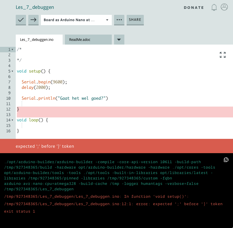
Check the error message in the red bar underneath the program. Do you see what is wrong?
If you check the program of Task 7.1 for syntactic errors, the IDE indicates expected ';' before '}' token. A token means something like symbol or character. So the IDE expected the character ";" for the character "}".
But where? Because there are more "}" characters in the program. Under the error message the black box describes the error message in more detail. It is still not easy, but if you often read quietly, it says exactly where the error is located.
The first red printed line indicates, for example, which function the error is in, In function 'void setup()':. The error is not in the function loop(), but in setup().
The next red printed line shows something that probably looks like Lesson_7_debugging.ino:12:1 error: expected ';' before '}' token. The text 12:1 indicates exactly where in the program the error is, line 12 and the first character. The IDE therefore despises an ";" for the "}" character.
Now use the indications in the error messages to solve the error from the program. Where would you put the ";" if you did it properly ?
Runtime errors are errors that occur during the execution of a program. If there is a runtime error in a program, it does not have to occur, but it can sometimes occur. Below you see a program which will have a runtime error when executing it. Start reading the program from the line int number = 5;. The program rules for this line make sure that the program chooses a random number. The random(1,10) function selects a random number from 1 to 10.
void setup() {
  Serial.begin(9600);
  delay(2000);
  pinMode(A1,INPUT) ;
  randomSeed(analogRead(A1));

  int getal = 5;
  Serial.println("start number");
  Serial.println(number);

  int counter = random(1, 10);
  Serial.println("start counter");
  Serial.println(counter);

  while (number != counter) {
    Serial.println("counter");
    Serial.println(counter);
    counter++ ;
  }

  Serial.println("Finished!");

}

void loop() {

}
First, the variable contains the value 5. This is then shown in the console of your IDE. Then a random number from 1 to 10 is placed in variable counter. Each time you start the program, a different value will be placed in it.
After that the program will repeat a number of program lines. The program will repeat these as long as the value of number is not equal to counter. Nothing seems wrong with that, is it not?!
Create a new program and, and call it Lesson_7_debug_runtime, cut and paste the above program lines into the program. Then hold a finger on the pin A1 of the Arduino. It doesn't matter if you touch another pin. Because you make contact with pin A1 a very small stream of electricity will flow from the computer to you. How much electricity goes through you varies at each time, this is used by the Arduino to generate a random number.
Then start the program a few times.
You can probably see that the program prints "Finished!" after a few numbers have been printed as shown in the example below.
.start number
5
start counter
2
counter
2
counter
3
counter
4
Finished!This is not always the case, if an error runtime error occurs in the program, the counter continues to run.
start number
5
start counter
8
counter
8
counter
9
counter
10
counter
11
counter
12
counter
13
counter
14
counter
15
counter
16
...
How come? Runtime errors are unfortunately not very easy to find. It is important that you work precise and try to debug the program step by step. Do this by going step-by-step through the program rules and writing down what the contents of the variables are and what the outcomes of conditions are.
Below is an example of how to write this down. Besides the contents of the variables is also the line number in the program where the variable changes value or the condition is tested. Now try to understand how the program works by following the steps below. On line 12 the variable counterwill get the random number 3.
Step     Line    Number    Counter   Number!=Counter
  1          8        5         -          -
  2         12        5         3          -
  3         16        5         3        True
  4         19        5         4          -
  5         16        5         4        True
  6         19        5         5          -
  7         16        5         5        False
Now try to write down the steps yourself as in the example above. Only the variable counteron line 12 gets here the random value 6.
Step     Line    Number    Counter   Number!=Counter
  1          8        5         -          -
  2         12        5         6          -
  3
As you see something goes wrong here. What do you have to adapt to the program to fix this bug?
You can already program and debug now! In the next lessons you will learn more instructions. In addition to the standard C instructions, this robot has special instructions for the robot. These instructions can be found in the Landje robot instructionset
.With this special instruction set you can let the robot drive, look, measure distance and recognize lines on the floor. By combining these functions in a program you can, for example, let the robot follow a line on the floor. But you can also let it drive around without bumping into anything.
In the next assignment, you will really make the robot move by means of the instruction move. It is an assignment in which you have to read and figure out things out, so take your time.
Now read the Landjerobot instructionset until the paragraph Instructions.
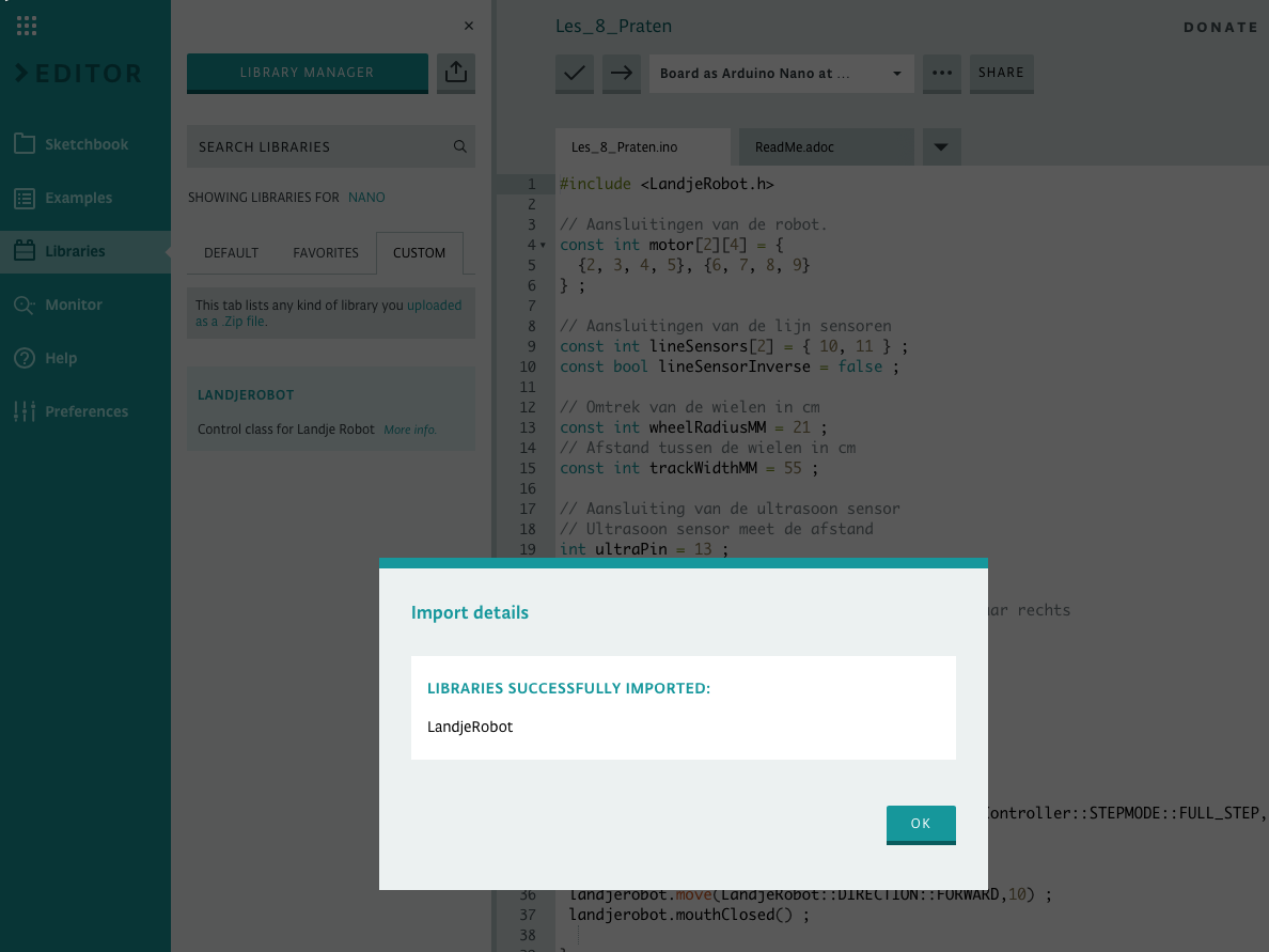
To use the Landjerobot instructions in your program, you must add the instructionset to the library of your IDE. A library is a collection of programs that belong together. For the Landjerobot, the library is named, you will probably guess it, LandjeRobot. Before you can add the library, you must first download it. You can download this library here
.After downloading the library you can add it to your IDE. In your IDE, click in the left column on Libaries. At the top of the second column is now LIBRARY MANAGER with to the right a symbol with an arrow pointing upwards. This is the import button. Click this button to import the just downloaded file LandjeRobot.zip. If this went well you will get a message as shown in the image.
Create a new program Lesson_8_robot_moves. Now use the Landjerobot instruction set to write an instruction in the function setup() that will make the robot move 10cm forward. Also don't forget to cut and paste the instructions shown at the top of the Landjerobot instructionset into your program. Before sending the program to the robot, make sure you set the ON/OFF switch to OFF.
Do you think the program is fine? Then remove the USB cable from the robot, put 4 batteries in the battery compartment and switch the robot on.
As you have seen, you can use the move instruction to move the robot forward. With another instruction turn you can turn the robot in one direction. How far you turn the robot is indicated in degrees. Take a look in the Landje robot instructionset at the instruction turn. At the picture of the robot you see a circle divided into 360 pieces, these pieces are called degrees. If you let the robot rotate 360 degrees, it makes a complete circle. At 90 degrees the robot makes a right angle.
By using the move and turn instruction you can make the robot drive a square. If you let the robot move forward first, and then rotate it has covered the first side of a square and is ready for the second side. If you repeat this four times, the robot will drive exactly a perfect square.
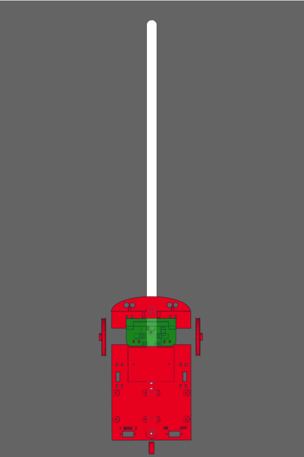
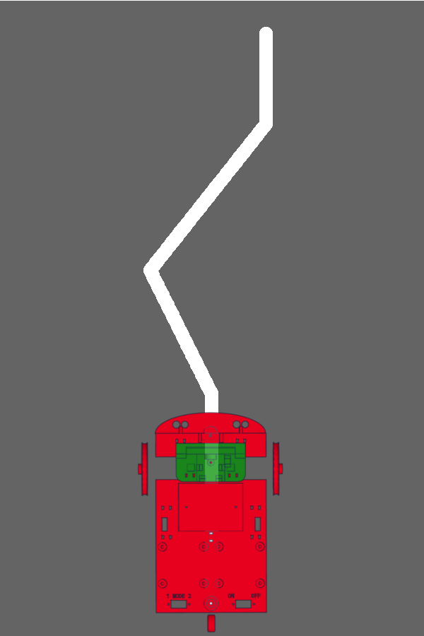
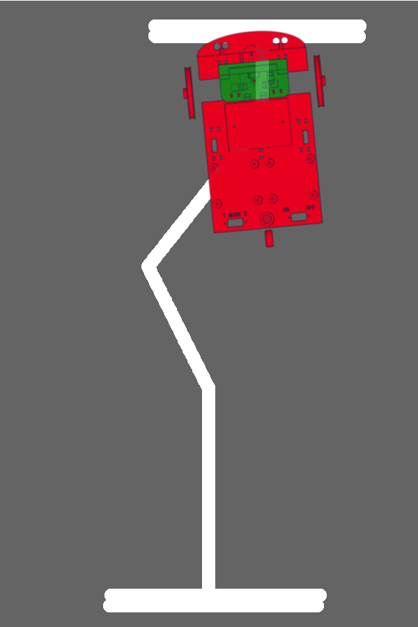
This may be difficult to understand in the beginning. What can help is by replaying the instructions yourself. Print out the image of the robot below, or draw it on a piece of paper. Then cut it out.
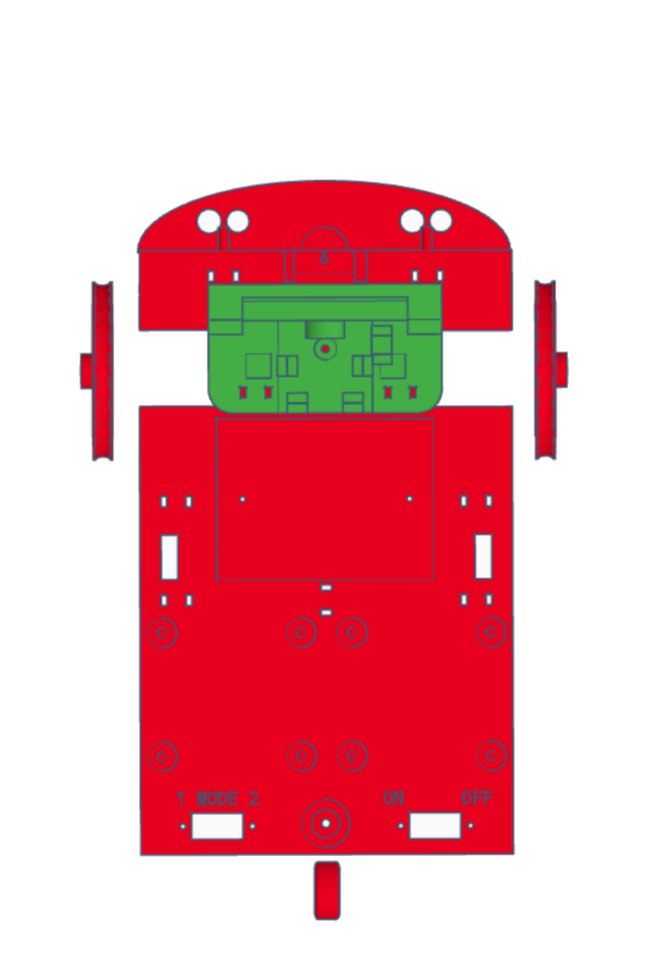
Now use the instructions below and use your paper robot to execute the instructions. Place the robot on a table and move it according to the instructions. If you follow these instructions, the robot will move into a square and return to the position where it started.
Move 10cm forward
Turn 90 degrees to the left
Move 10cm forward
Turn 90 degrees to the left
Move 10cm forward
Turn 90 degrees to the left
Move 10cm forward
Turn 90 degrees to the leftYou know how to drive the robot in a square and you can program it yourself. The move and turn instructions have a different syntax . For example, for the instruction move you have the syntax move( direction , distance) ; and move( direction , distance, waiting) ;. Syntax is how an instruction is composed.
The difference between the two syntaxes is that the first syntax can only specify the direction and distance. With the second syntax you can also indicate that the instruction waits until the action, moving the robot over a distance, is finished. If you don't indicate in the move and turn instruction that it has to wait until it is finished, the robot will have completed all move and turn instructions before the robot has driven an inch!
Now create a new program "Lesson_8_move_square" and program in the function setup() the instructions to move the robot in a square.
If you think the program works properly, upload it to the robot and turn it on. Don't forget to remove the USB cable!
Dry is an abbreviation that every programmer knows. It is the abbreviation of Don't Repeat Yourself. You probably wrote four times the move and turn instruction in Task 8.2. This is good, but what if you want the robot to drive a 15 centimeter square instead of a 10cm square? Then you have to change the program in 4 places! So it is better to avoid repetitions of instructions in programs. So if you program, DRY!
Pas het programma van Opdracht 8.2 aan zodat je nog maar èèn keer de move en turn instructies gebruikt om de robot in een vierkant te laten bewegen. Heb je even geen idee hoe je dit zou moeten doen, kijk dan eens in hoofdstuk 6, succes!
Landjerobot has several sensors. Sensors with which you can measure distance, a switch and reflection sensors. These sensors can be used to detect a line on a floor. These sensors work best on a dark floor that has a uniform color. On this floor you will soon stick a piece of white tape so that the sensor can detect it.
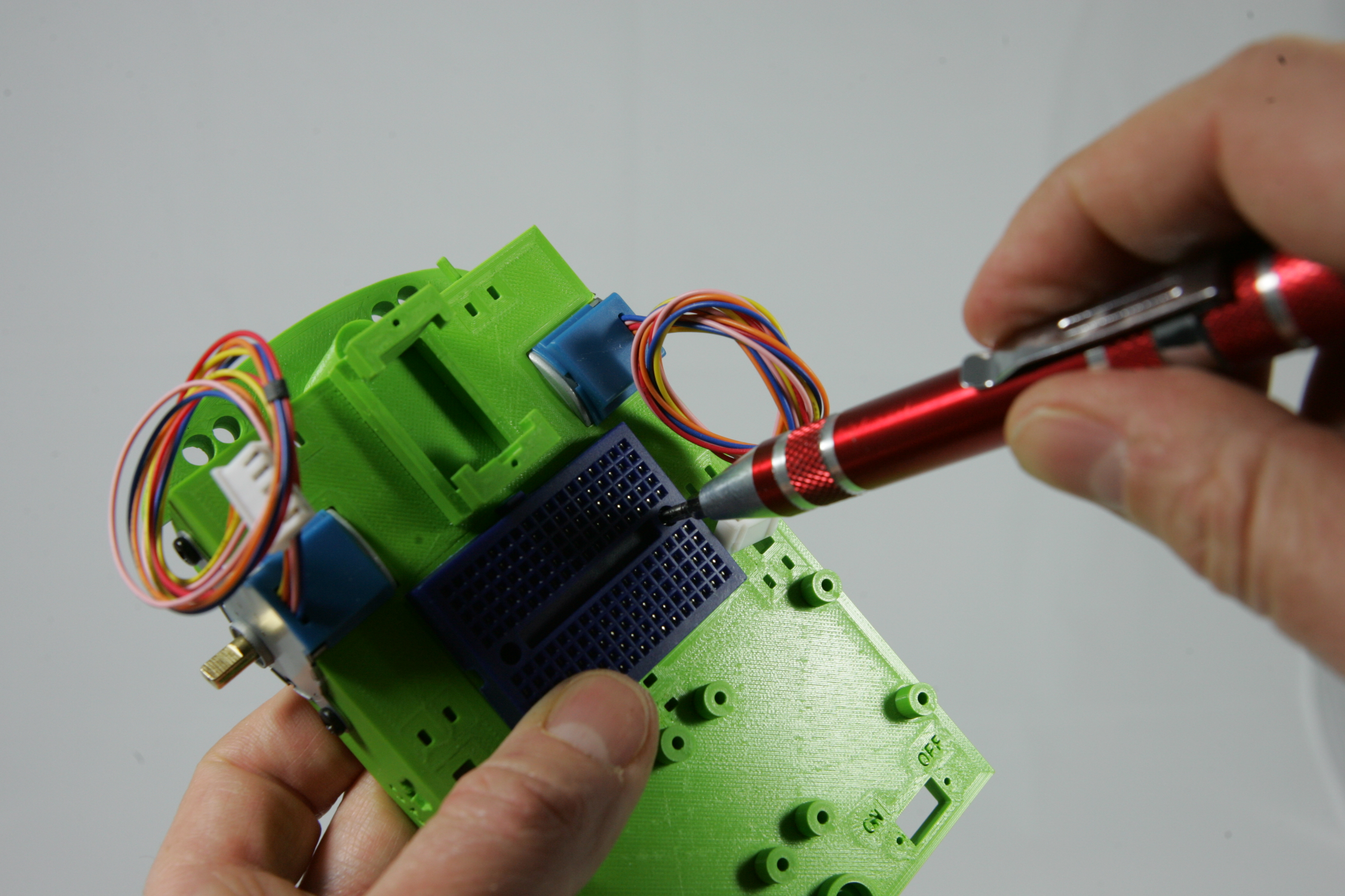
In this command you will adjust the reflection sensors. The sensors give a light that is invisible to humans and then can detect if that light is reflected. You can adjust these sensors to give a signal when a certain amount of light is reflected. So it is best to use the sensor on a dark floor with white tape or a light floor with a dark tape so that the sensor can best detect the difference between floor and tape. You have to adjust the reflection sensors differently when driving on a dark floor than on a light floor. In this task you can find the right steps for your floor to adjust the reflection sensors properly.
Because you will have to turn on the robot to adjust the sensors, it is useful that it does not start to drive at once. So create an empty program in your IDE and upload it to the robot.
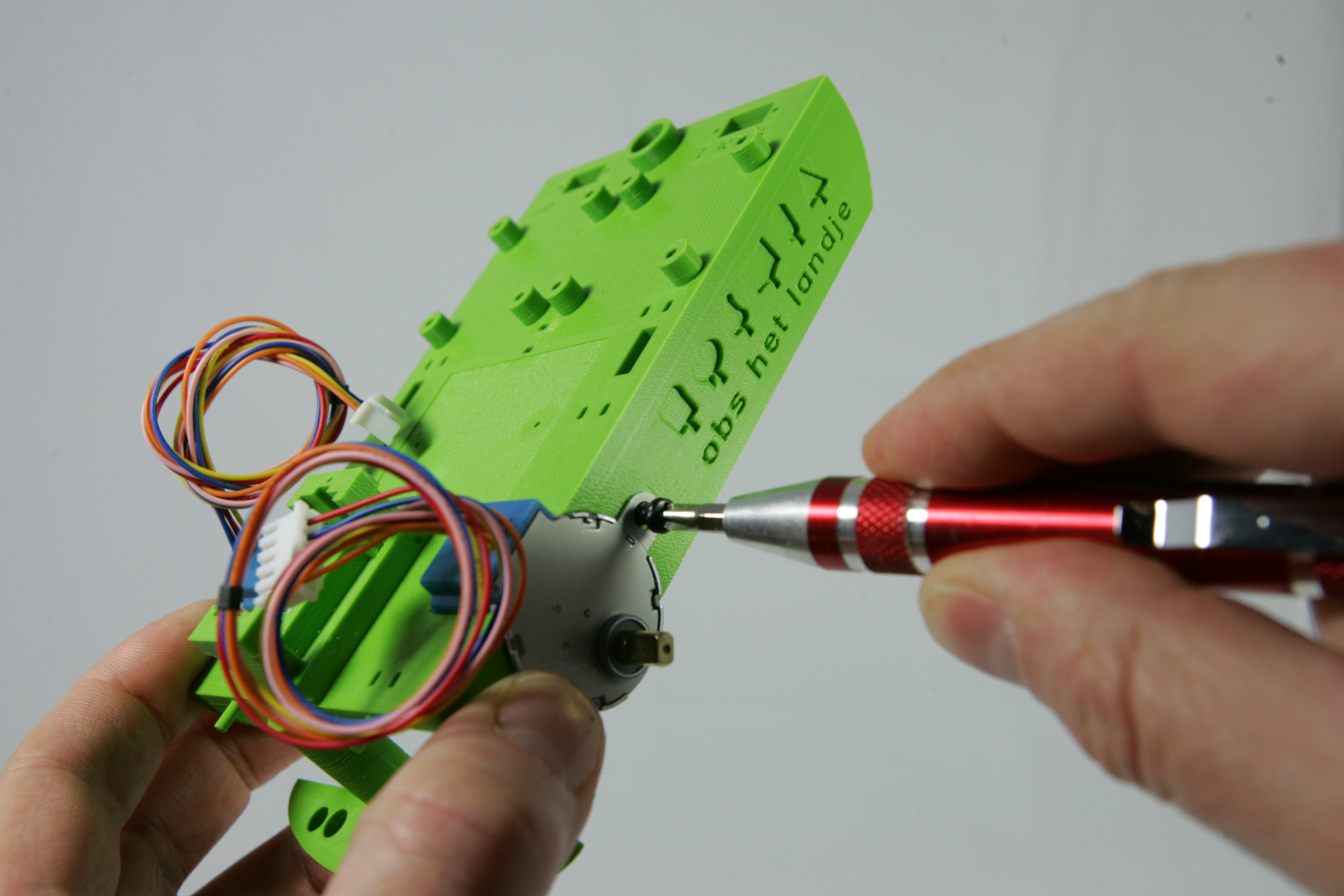
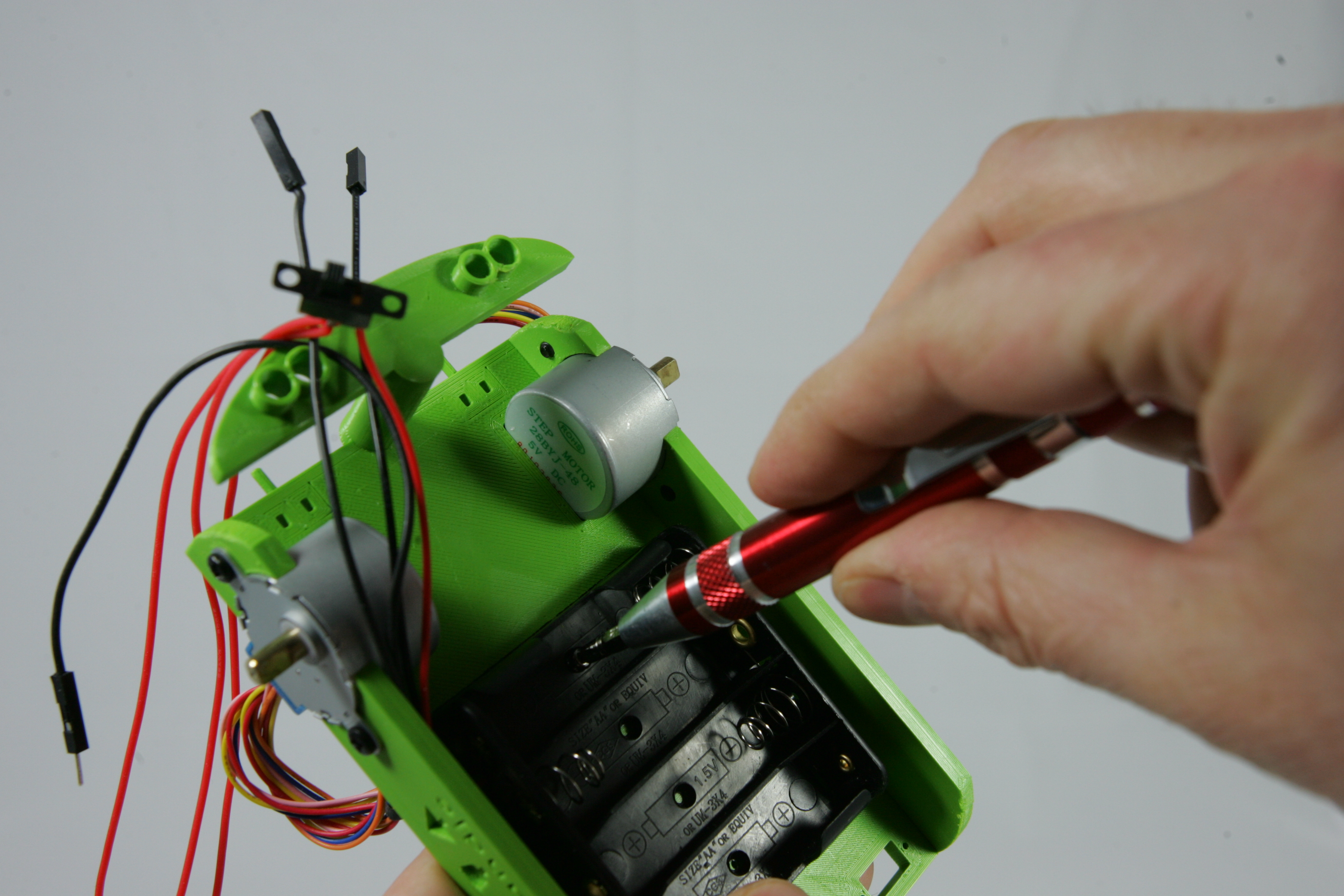
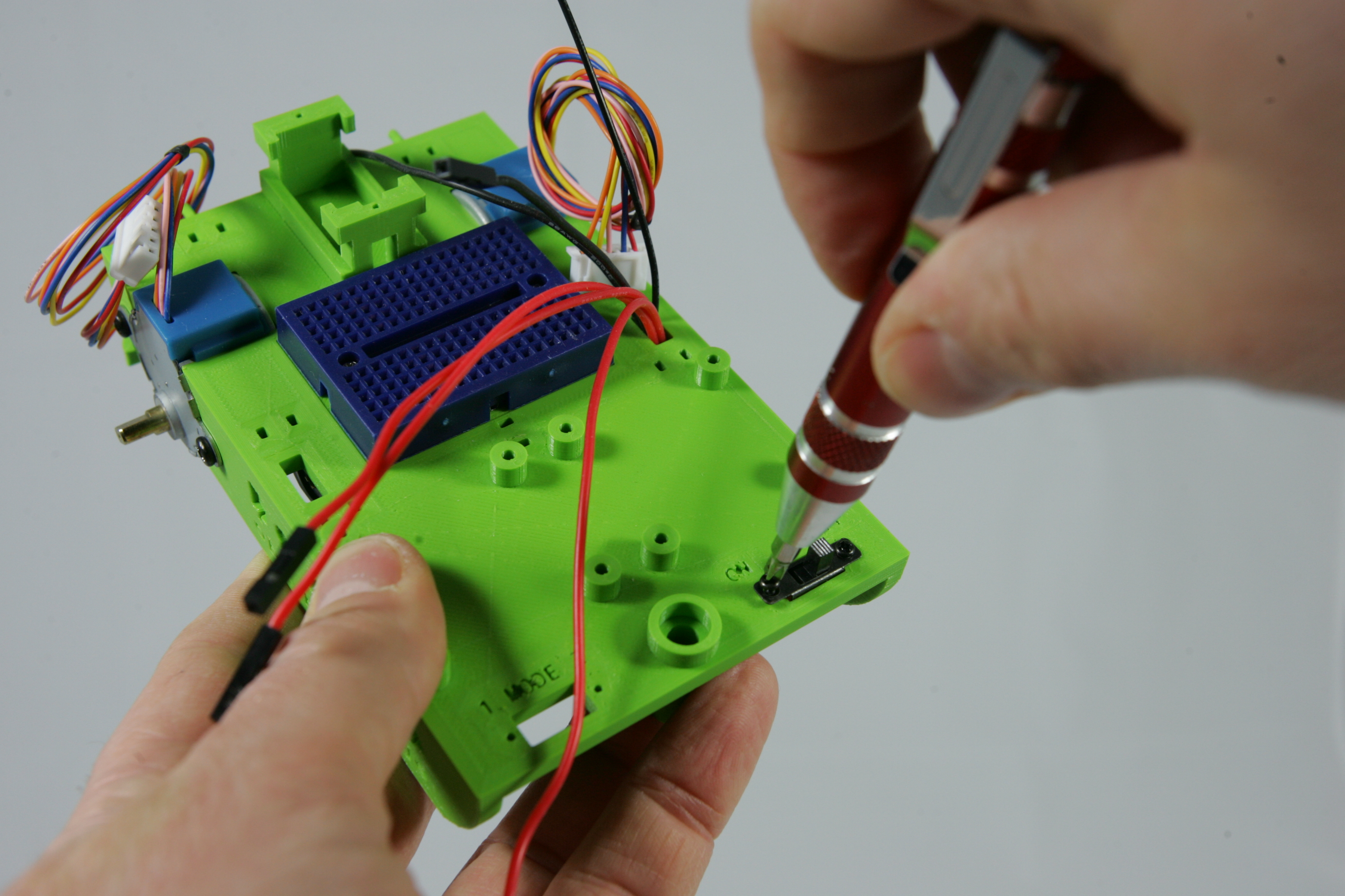
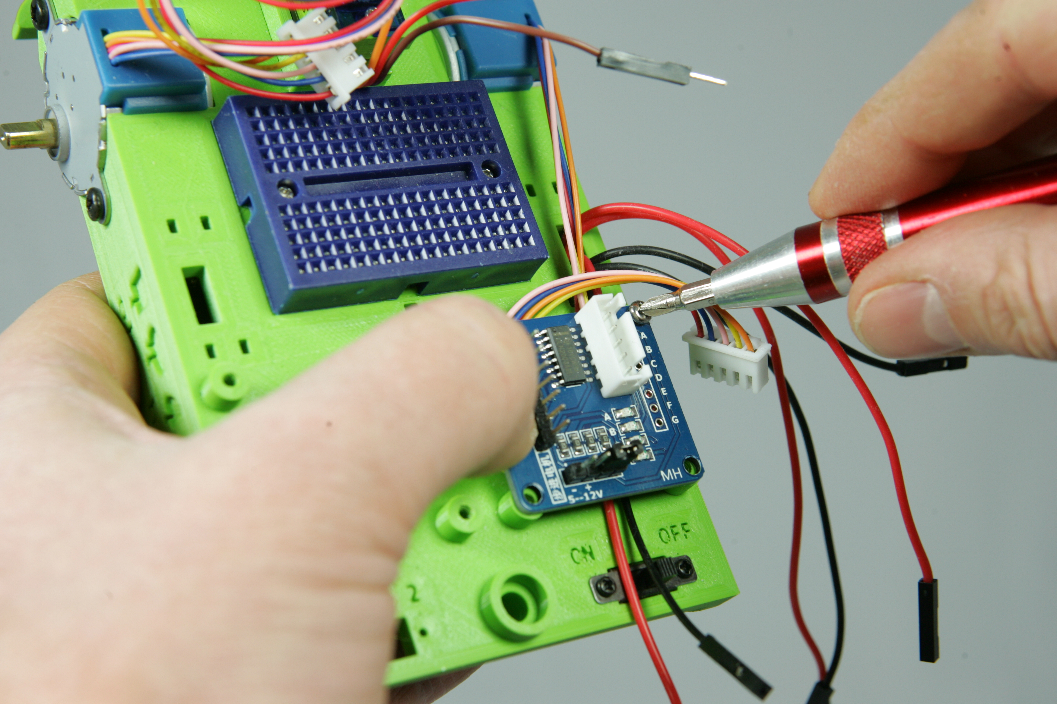
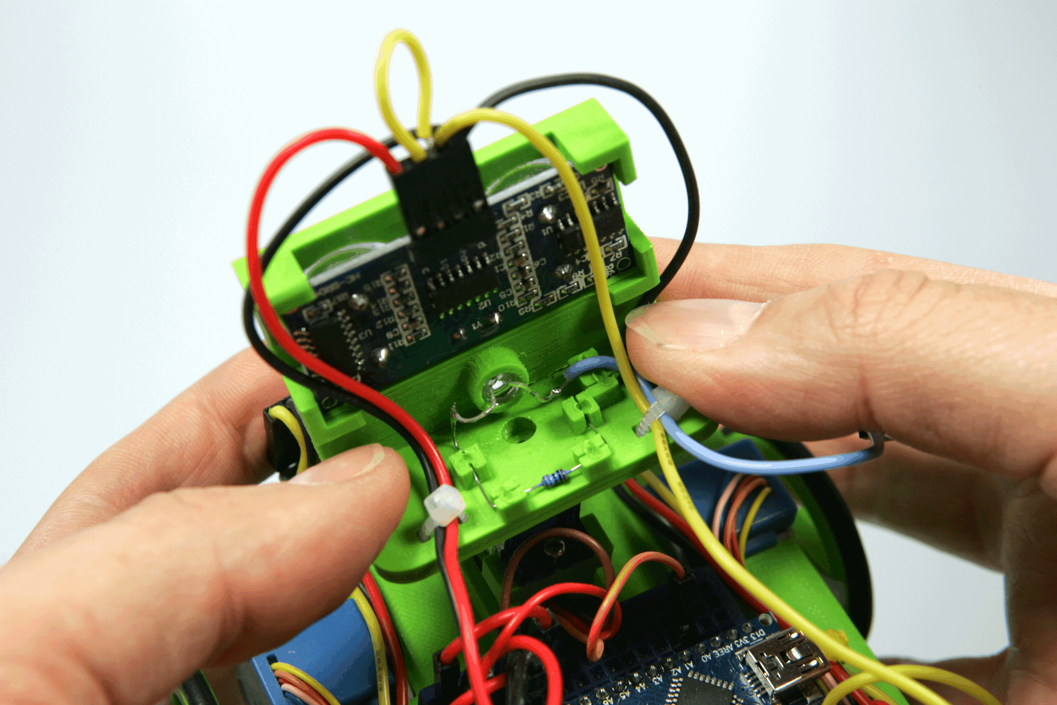
light coloured floorUnplug the USB cable from the robot and turn it on. The reflection sensors have a small blue block with a small screw hole in the middle. Take the smallest Phillips screwdriver (the one in the shape of a cross) and carefully turn the screws of both sensors to the left. Now stick a piece of black tape on the floor and place one of the sensors above the black tape. If all goes well, only one LED on the sensor will be lit. Then slowly turn the screw to the right until a second LED lights up, then stop turning the screw. Repeat the same steps for the other sensor.
dark coloured floorUnplug the USB cable from the robot and turn it on. The reflection sensors have a small blue block with a small screw hole in the middle. Take the smallest Phillips screwdriver (the one in the shape of a cross) and carefully turn the screws of both sensors to the right. Now stick a piece of white tape on the floor and place one of the sensors above the white tape. If all goes well, only one LED on the sensor will be lit. Then slowly turn the screw to the left until a second LED lights up, then stop turning the screw. Repeat the same steps for the other sensor.
When starting a new program for the robot you always have to copy some lines from the Landjerobot instructionset. One of these lines looks like this.
const bool lineSensorInverse = true ;If you have a dark coloured floor, you must change this line for every program you create to
const bool lineSensorInverse = false ;By changing the value from true to false, the robot knows that you use a light coloured line on a dark floor, instead of a dark coloured line on a light coloured floor.
With the instruction detectLine() you can test if the robot detects a line and on which side, the left or right. If you read in the Landje robot instructionset, you will see that this instruction can return four different values. Which value is returned, depends on which sensor or sensors detects a line.
Now write a program that will let the robot drive straight ahead and stop if one of the sensors detects the white or black tape. Start with the instruction move(direction); so that the robot will start driving and does not wait until the instruction is finished. Put this instruction in the setup() function. The setup() is only called once, when you switch the robot on. This will cause the robot to start driving when you turn it on, and it will no longer start driving after it has stopped. Then write in the function loop() your program that makes sure that if the sensor does detect a line it stops the robot.
The detectLine instruction can return four different values LandjeRobot::LINE::NONE, LandjeRobot::LINE::LEFT, LandjeRobot::LINE::RIGHT and LandjeRobot::LINE::BOTH. So the robot must stop if it returns the value LandjeRobot::LINE::LEFT, LandjeRobot::LINE::RIGHT or LandjeRobot::LINE::BOTH. Perhaps you could also write this by using only LandjeRobot::LINE::NONE ? That would make writing the code for stopping the robot much easier!
In this lesson you will learn to program sensors. With sensors you can observe things, like for example the reflection sensors, the difference between light and dark surfaces on a floor. With the data from this sensor you can then make the robot respond to this.
You have already learned how to assemble the robot, write simple programs and let the robot drive and stop with robot instructions. In this lesson you will learn how to let the robot drive independently along a line.
By using the reflection sensors you will detect when a sensor passes a line. If it goes over a line you will have to do something to make sure the robot will follow the line again.
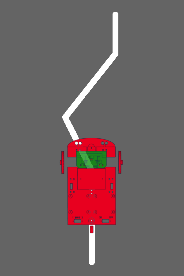
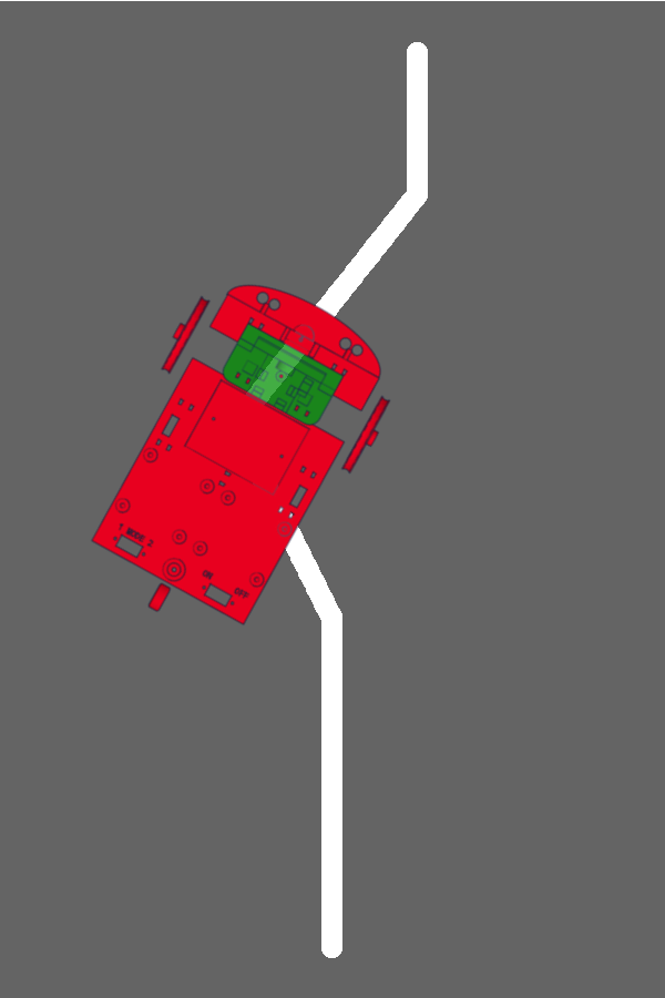
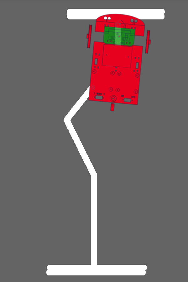
In the example on the right, if the robot continues to drive straight ahead, it will not cross the line with the reflection sensors at all. You don't have to adjust the robot to let it follow the line.
Then one of the reflection sensors will detect the line at some point.
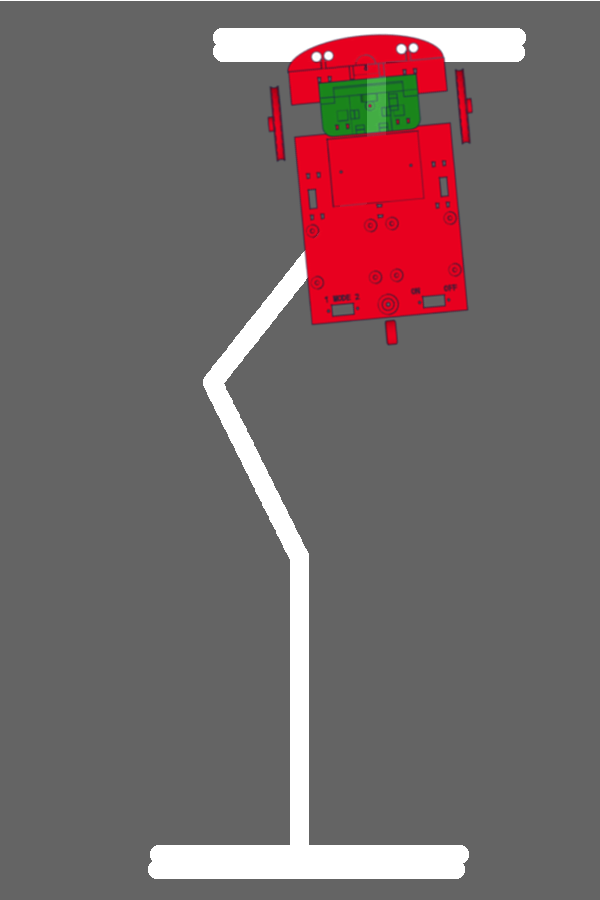
In the example on the right, the left reflection sensor will detect the line first. In the program below you let the robot drive straight ahead and print a letter. Which letter is printed depends on what the sensors detect. Which letter do you think will be printed when the robot is as shown in the picture on the right?
void setup() {

   Serial.begin(9600);
   delay(2000);

   landjerobot.move(LandjeRobot::DIRECTION::FORWARD) ;

}

void loop() {

  if (landjerobot.detectLine() == LandjeRobot::LINE::NONE) {
    Serial.println("A");
  }

  if (landjerobot.detectLine() == LandjeRobot::LINE::LEFT) {
    Serial.println("B");
  }

  if (landjerobot.detectLine() == LandjeRobot::LINE::RIGHT) {
    Serial.println("C");
  }

  if (landjerobot.detectLine() == LandjeRobot::LINE::BOTH) {
    Serial.println("D");
  }

}
If the left sensor detects a line, the robot must also turn to the left to continue following the line.
Now stick pieces of tape on the floor of about 1 meter that the robot has to follow. Make a few bends here and there, as shown in the pictures above. Do not make them too sharp otherwise the other sensor will detect the line during the rotation of the robot and the robot can get stuck.
Now create a new program in Arduino Create. Give the program the name "My_Robot". In the following tasks you will expand this program further and further. Now program the robot to follow the line. In short you must make the robot:
setup() function when you turn the robot onloop() In this task it is the first time you will use the turn instruction. Find in the Landje robot instructionset how to use the instruction. Think carefully whether you let the move and turn instruction wait till it is completed and continue with the next instruction.
Do you think the program is fine? Then test it out! If the program does not do what you expect of it, try to debug what goes wrong. It helps if you try to replay the program with the "paper robot".
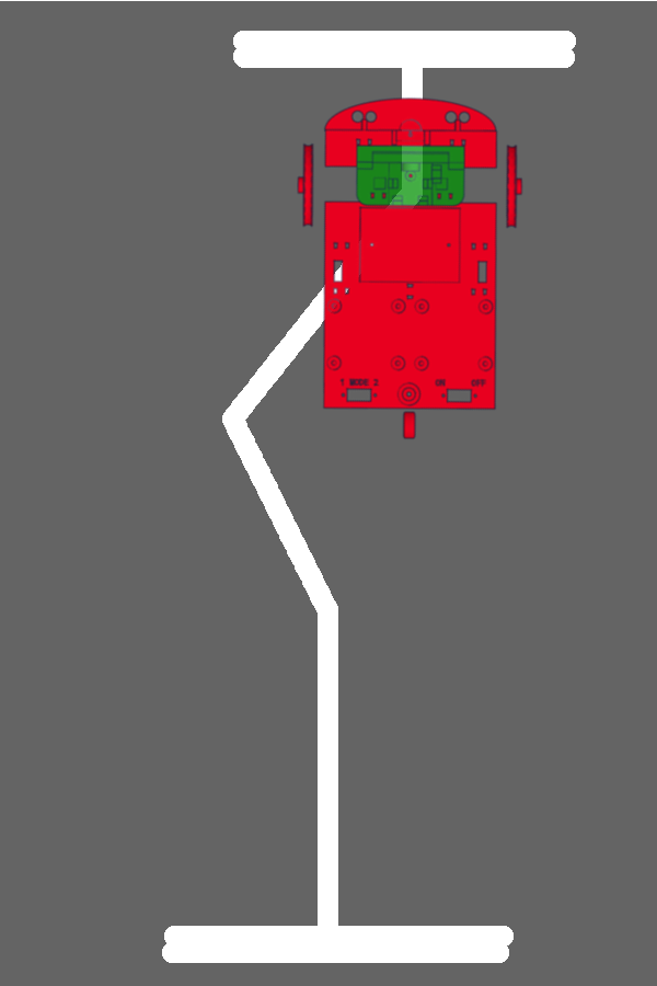
The robot will, if all went well, follow the line on the floor. But at the end of the line the robot will continue driving. It will continue straight ahead because no line is detected anymore.
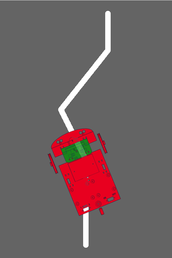
If you can let the robot turn at the end of the line, it will keep following the line. First from bottom to top, as shown in the picture on the right. Then when he turns he will drive from top to bottom again.
By pasting a line perpendicular to the beginning and end of the line to be followed, the robot can detect that it has to turn.
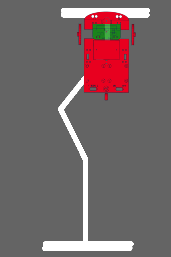
When the robot drives over this "full turn line", the left and the right reflection sensor will detect a line.
If the robot sees both lines at the same time, it can turn 180 degrees and continue following the line again.
The robot will then follow the line in reverse order until it detects another "full turn line". Then it will make a full turn again and the line tracking will start again.
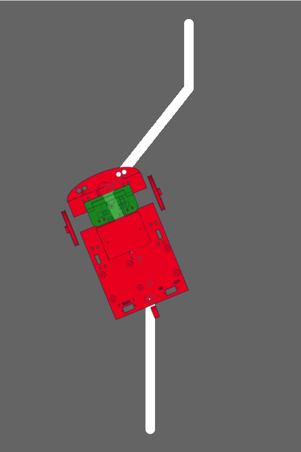
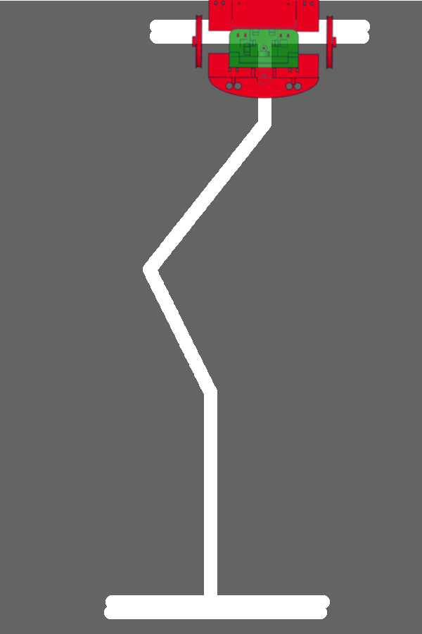
But what happens if the robot does not see the "full turn line" exactly with both sensors at the same moment? Look at the picture on the right. The right sensor sees the "full turn line" just before the left sensor..
What would happen if you let the robot drive with the program of task 9.1?
The right sensor detects that there is a line. There is something in your program that probably looks like this;
if (landjerobot.detectLine() == LandjeRobot::LINE::RIGHT) {
    landjerobot.turn(LandjeRobot::TURN::RIGHT,10,true) ;
}
The robot turns to the right when the right sensor detects a line. This will bring the left sensor above the "full turn line", but the right sensor will be next to the lineagain. So the robot will still not turn. Do you know what the robot will continue to do?
So the robot continues to wobble back and forth for the "full turn line". It keeps doing this until the batteries are empty.
Now try to think up with your paper robot and your program of task 9.1 how you can prevent the robot from wobbling for the "full turn line". How can you prevent the robot from going immediately to the left or right if it doesn't end up perfectly straight on the "full turn line"?
Tip: Take a look in the Landje robot instructionset at the instruction delay, might you be able to do something with this instruction?
Stick the turn lines with tape at the beginning and end of the line the robot should follow. Make the lines wide enough, about as wide as the wheels of the robot are apart. Make the turn lines twice as thick by sticking two strips of tape next to each other.
Because you probably created your own solution in assignment 9.1, you will continue with the solution as shown below. Copy the solution below for command 9.1 into your program, "My_Robot". There are also some comments explaining what the instructions do. So try to understand this program before you continue.
void setup() {

       // Start moving in forward direction and
       // do not wait till the instruction is completed
       landjerobot.move(LandjeRobot::DIRECTION::FORWARD) ;

}

void loop() {

    // If the sensor does not detect nothing (!)
    // then act
    if (landjerobot.detectLine() != LandjeRobot::LINE::NONE) {

        // If the reflection sensors do detect a line on the left
        if (landjerobot.detectLine() == LandjeRobot::LINE::LEFT) {
            // Turn 10 degrees to the left and wait till the
            // instruction is completed
            landjerobot.turn(LandjeRobot::TURN::LEFT,10,true) ;
        }

        // If the reflection sensors do detect a line on the right
        if (landjerobot.detectLine() == LandjeRobot::LINE::RIGHT) {
            // Turn 10 degrees to the right and wait till the
            // instruction is completed
            landjerobot.turn(LandjeRobot::TURN::RIGHT,10,true) ;
        }

        // Let the robot drive on again
        landjerobot.move(LandjeRobot::DIRECTION::FORWARD) ;

    } // end if

}
Expand your program now. Make sure the robot turns around at a "full turn line". When it is turned around, the robot should follow the line again in the other direction, and then turn around at the next "full turn line" again.
The robot must turn when both the left and right reflection sensors do detect a line. To program this you can use the existing program lines rotating the robot to the left and right as an example.
Then you have to make sure that the robot does not wobble before the "full turn line". Program what you came up with in task 9.2 to make the robot turn properly and try if it works. Can you not get it to work? Then try to debug what goes wrong. It helps if you go through the program step by step again with your paper robot.
You now have a program ready that makes sure the robot drives along a line and turns on a "full turn line". Later you'll program the robot to drive around and avoid other robots and objects. It would be useful if you can save both programs into the robots memory and decide which program to execute when you switch the robot on.
For this you need something to be able to pass your choice on to the robot. You can do this without having to connect the robot to a computer again with the mode switch. This switch has two positions, 1 and 2. By means of the instruction mode you can determine which position the switch is in.
In this task you will make sure that the robot only starts your "line follow" program in, "My_Robot", when the mode switch is set to "1". If the switch is set to "2", the robot is not allowed to do anything. Later you will make sure that another program is started in position 2.
mode works in the Landje robot instructionsetmode of the type int before the function setup() and give it the value 0. If you create a variable in a function, you can only use it in this function. For example, if you create the variable mode in the setup() function, you cannot use it in the loop() function. The function loop() then does not know this variable. If you create a variable before the function setup() and loop() you can use it in both functions.
setup() , write a piece of program that causes the variable mode to get the value from the instruction mode.setup(), let the robot only start driving if the variable mode has the value "1"loop function in your program so that the instructions as you completed in task 9.3 will only be executed if the switch is in position 1 when starting the robot.If all went well, you'll have the first program of the robot ready now! Test the program now.
In the head of the robot of the robot are an ultrasonic sensor and a led. The ultrasonic sensor can measure distance with a sound that is not audible to us. It measures a distance by making a sound and waiting until the echo of this sound comes back. By means of the time that lies between the sending and receiving of the sound, the computer can calculate the distance. The led in the robot's mouth can blink so it looks like it's talking. You can also turn the led on or off and detect if it is flashing.
The head of the robot comes on a motor. This is not just a motor, but a servo motor. A servo motor can't rotate continously. This motor can turn the shaft exactly half a circle, 180 degrees, to the left and to the right. Because the motor knows exactly in which position the shaft is, you can indicate how many degrees it should move to the left or right.
Later on you can use the instruction look to steer the direction of the axis. The axis can then be rotated 45 and 90 degrees to the left and right and positioned exactly in the middle. By rotating this axis you can later, after securing the robot's head, make it look to the left and right.
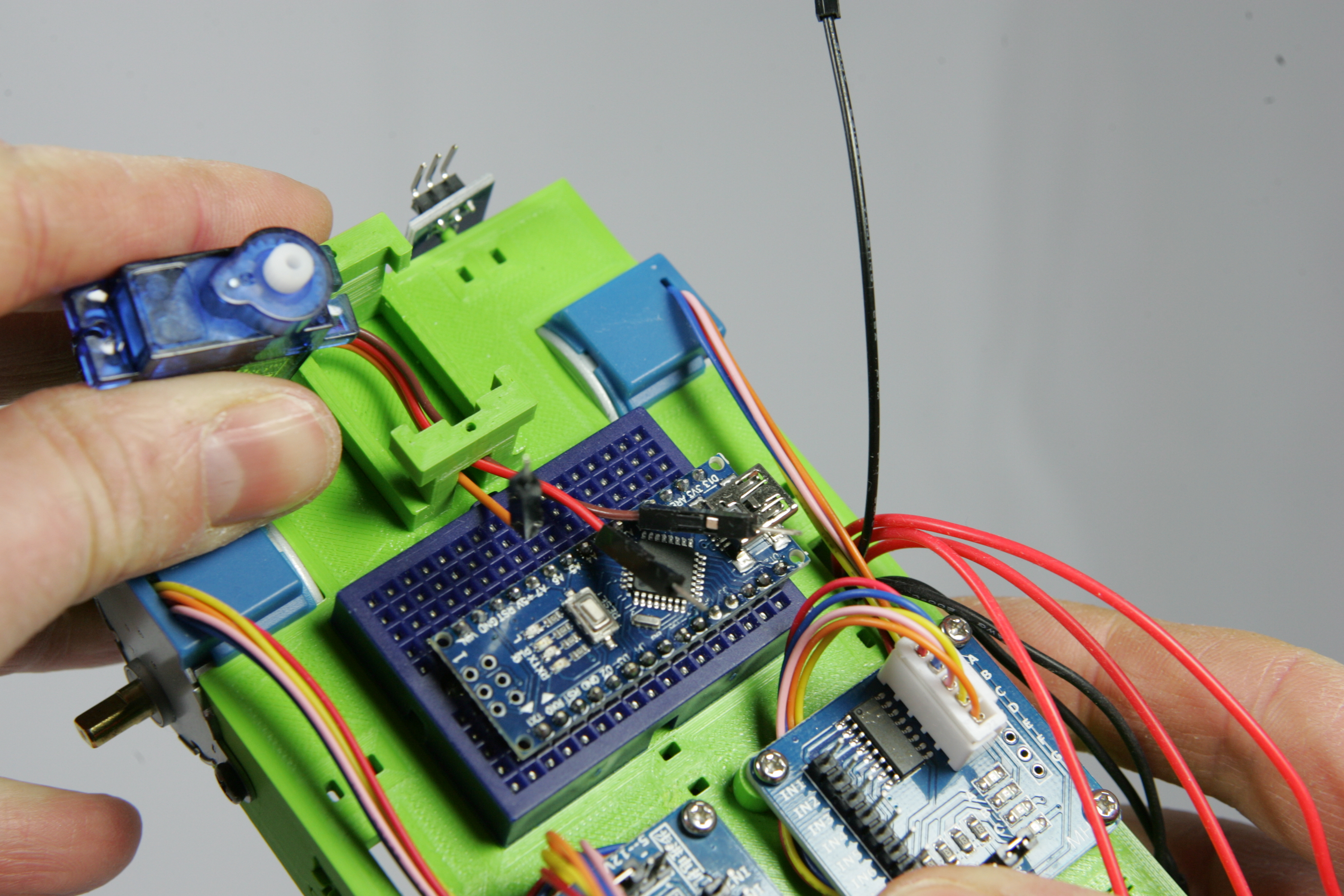
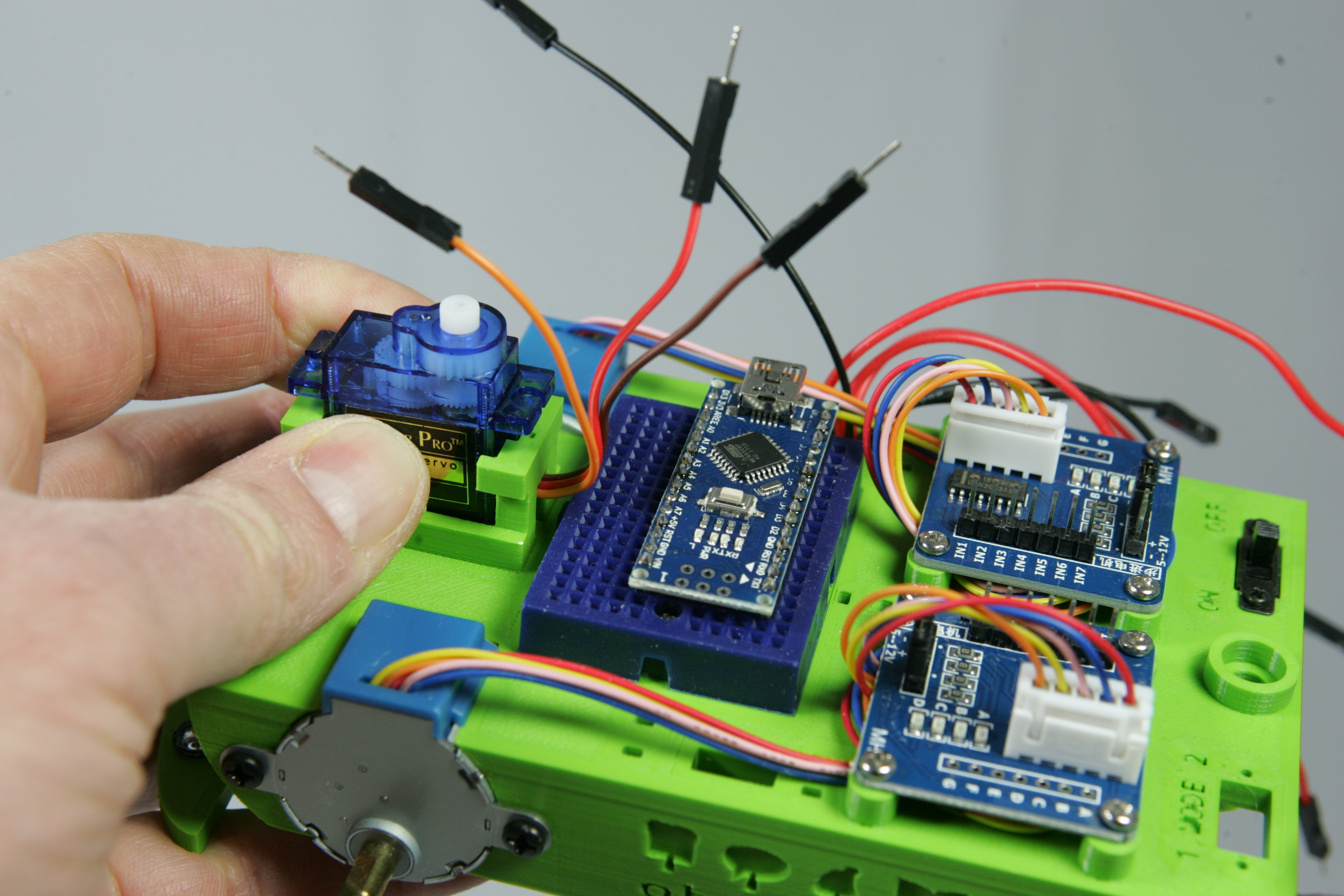
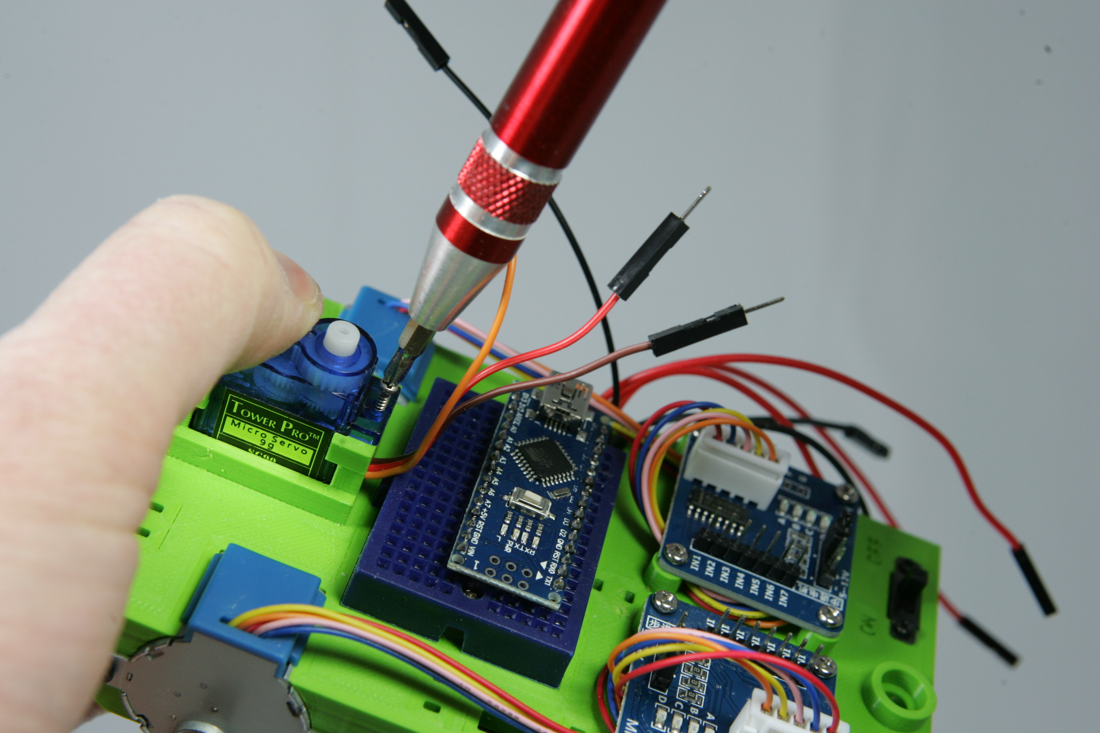
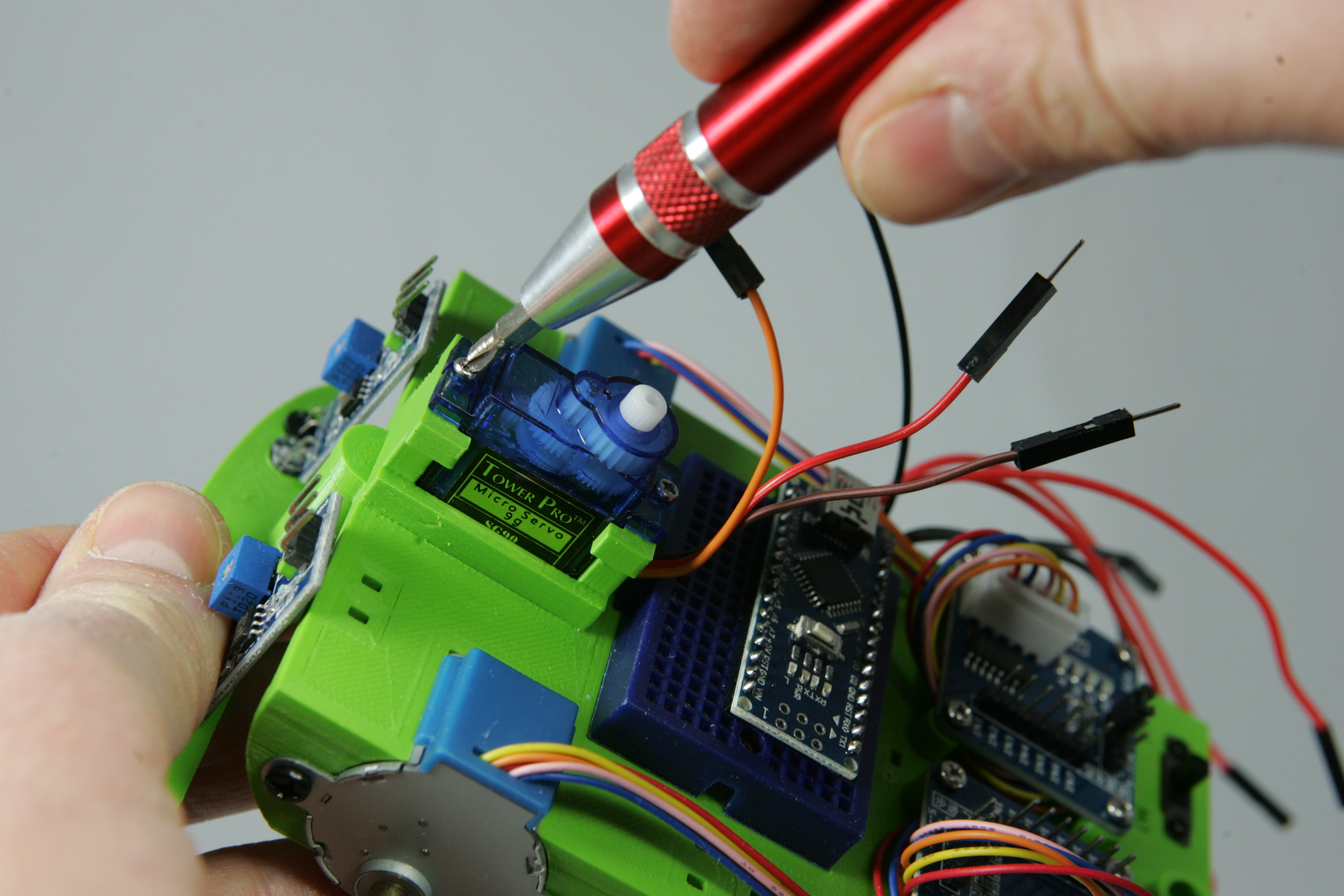
Now it is so handy that you know in which position the motor is before you screw the head onto the servo motor. Otherwise there is a good chance that the robot always looks in another directon than you want it to look. Therefore, first make sure that the shaft of the servo motor is exactly in the middle before you attach the head of the robot.
Open the Landje robot instructionset and read the description at the instruction look. You are now going to write a new temporary program that you will only use for the correct setup of the servo-motor.
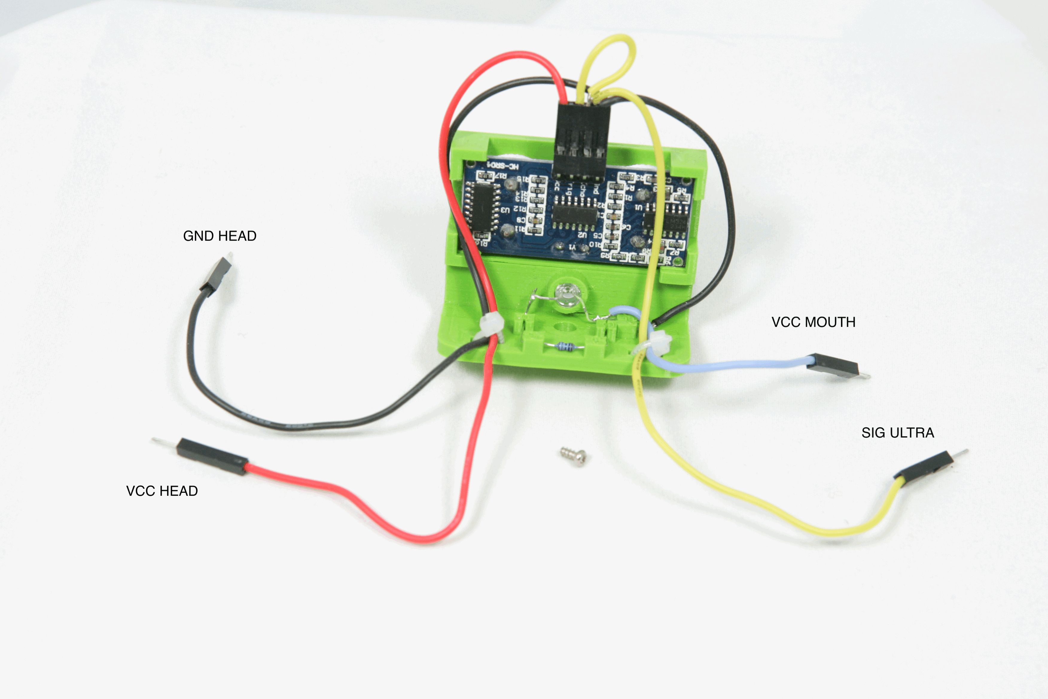
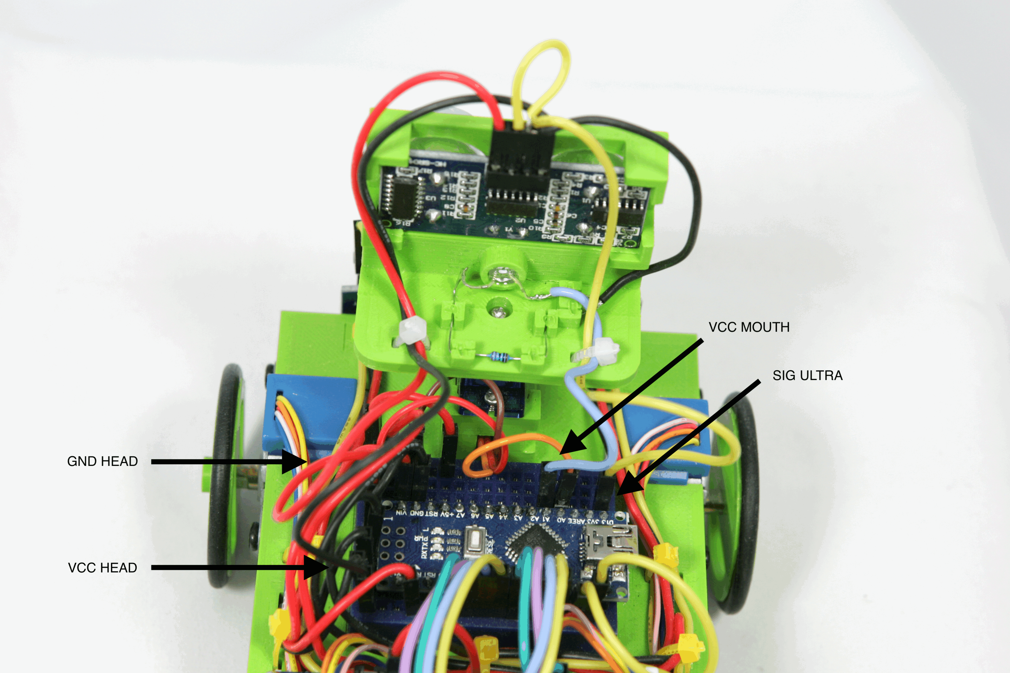
The robot is now complete, only the wires of the sensor and the led-light on the head of the robot have to be connected. On the head of the robot are four wires GND HEAD, VCC HEAD, VCC MOUTH, SIG ULTRA.
Connect the GND HEAD wire to the bottom leftmost row of the breadboard that is connected to GND. The VCC HEAD wire must be connected to the top leftmost row.
With the GND HEAD and VCC HEAD you make sure that the sensors and the LED on the head of the robot are connected to the battery. Now you have to connect the wires to receive the signal from the ultrasonic sensor and to turn the LED on and off. Connect the wire VCC MOUTH to pin 15 of the Arduino, then connect the last wire SIG ULTRA to pin 13.
The robot now has a mouth with which it can 'talk' and a pair of eyes with which it can really look. In the following assignments you will learn how to let the robot look and talk.
When you have connected the head of the robot, the robot is complete. On the head of the robot are the ultrasonic sensor with which you can measure distances. There is also a led in the mouth that you can turn on, off and blink. You can turn the LED on or off. You can also make it blink for a few seconds. Search in the Landje robot instructionset the instructions you need for this. Create a new program, "Lesson_10_mouth" and try out these three instructions. For example, write instructions that illuminate the led, turn it off and make it blink. Between these instructions you can use the delay() instruction to wait a while between the instructions.
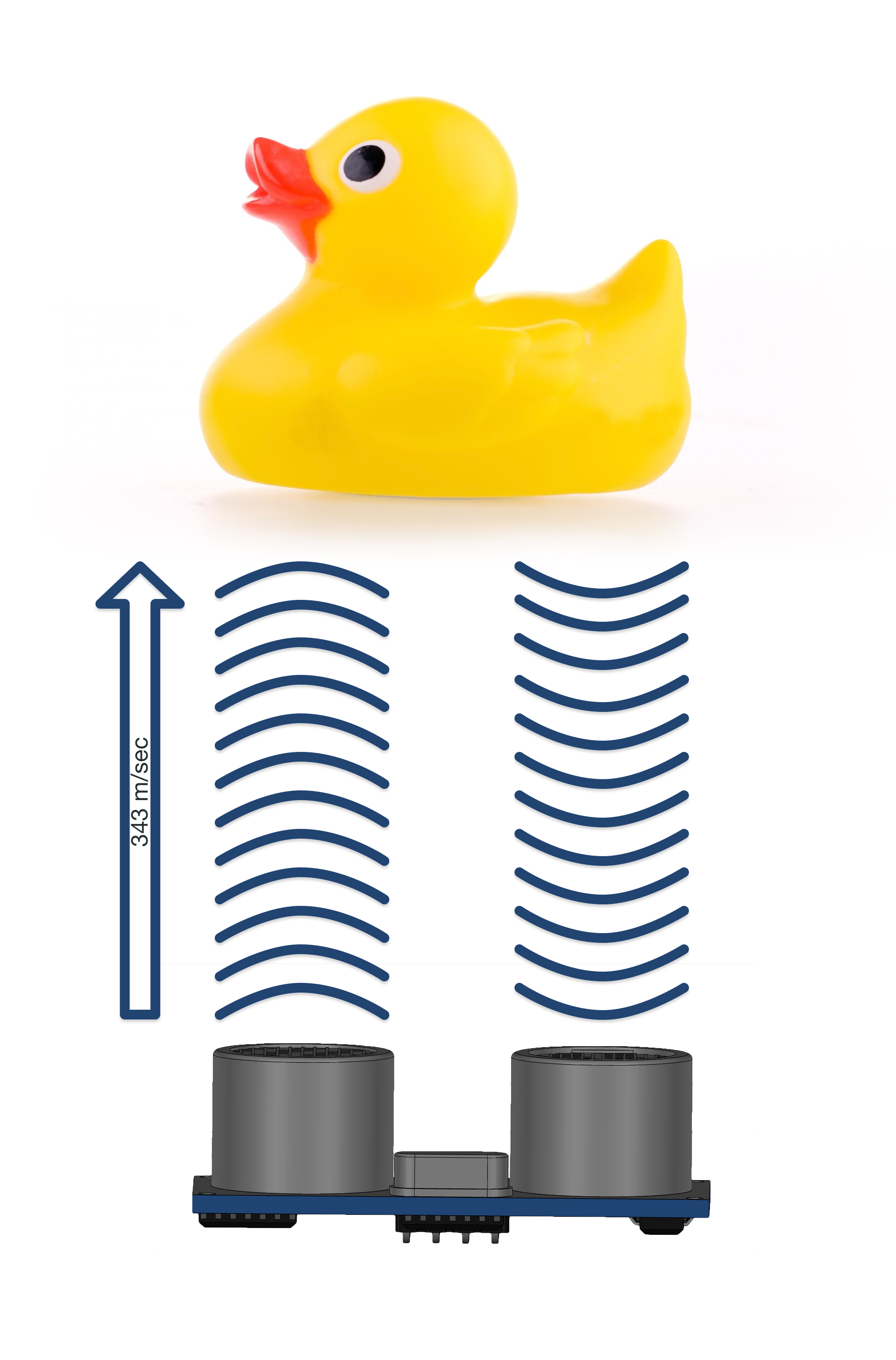
In the head of the robot is an ultrasonic sensor to measure distances, but how does it actually work? When the sensor starts measuring the distance, it makes a sound. This sound is a high beep that we humans cannot hear. This sound goes in the direction where the sensor is pointing. When the sound comes something on its way, the sound is reflected and comes back to the sensor. The reflection of sound is called 'echo'. Once the sensor has received the sent sound again, it measures how long the sound has been on its way from the sensor to the object and back again.
Sound moves at a speed of about 343 meters per second or over 1200 km/h! Because we know how fast sound moves, we can use the measured time to calculate the distance between the sensor and the object.
If you scream at a mountain in the mountains you will hear the echo after 12 seconds. Calculate how far the mountain is from you.
In this command you will have the robot measure distance using the ultrasonic sensor. Create a new program in the Arduino Web editor, Lesson_10_measure_distance
.To make it a bit easier you get the program below. Cut and paste this program in the new programs Lesson_10_measure_distance function setup(). Then replace the 3 places with ... with the correct instructions
void setup() {

    int afstand = 400 ;

    Serial.begin(9600);
    delay(2000);

    // druk de gemeten afstand af zolang
    // de afstand groter is dan 5 cm.
    while (...) {
      ...
      Serial.println(afstand) ;
    }

    // Laat de robot 10 seconden praten
    ...

}
Test the program by starting the program and opening the monitor in the Ardunio Web editor. Now move your hand very slowly towards the sensor. If all goes well, the robot will start 'talking' if you are less than 5 cm from the sensor.
In the previous lessons you wrote the first program for the robot. This program allowed the robot to follow a line and reverse at the end of a line. You started this program by making sure that the mode switch was set to "1" when you turned on the robot.
In the next lessons you will expand the program. This extension of the program will be started when the mode switch is set to "2" when the robot is switched on.
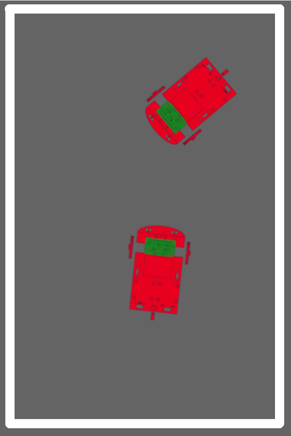
Instead of following a line, you will now move the robot within an area. This area is created by marking the outside with tape on the floor, just like on the example on the left. If the robot detects a line while driving, the robot has to turn and move on within the area.
In addition, you are going to use the robot's eyes, as it can now see whether there is anything that needs to be driven around.
It's time to use your paper robot again! Take a sheet of paper and draw a rectangle with a thick marker as shown in the image on the right. Place your paper robot in the rectangle and drive with it.
Now look at how many ways the reflection sensors of the robot can touch the lines. Describe per way what the robot has to do to stay within the lines. Write this down as follows; "If the [left | right | both] sensor detects the line, then ... and then ... ".
So for example: "If the left sensor detects the line, then turn 10 degrees to the left and then move forward."
In task 11.1 you have now thought about what the robot has to do to stay neatly within the lines on the floor. The program rules you are going to write to do this have to be repeated as long as the robot is moving. These program rules have to be placed in the function loop(). Only something is needed in the function setup() to get the robot to start properly.
Pack the roll of tape and use it to make a rectangle on the floor. Make the rectangle big enough for the robot to drive around in it. But don't make it so big that it takes a long time before the robot touches a line. Later in the lessons you will be allowed to make a much larger rectangle. Now a length of one to one and a half meter per side of the rectangle is very nice.
Are the lines tape nicely? Then you can try out the robot. Put the robot in the middle of the rectangle and set the mode switch to position 2. Then turn on the robot, and what happens ?
Yes, something is missing. The robot should do one thing as soon as you turn it on! Open the program "My_Robot" and adjust the function setup() so that the robot does what it should do after you turn it on! You don't know what the robot should do ? Then set the mode switch to 1 and turn on the robot. Now you know!
yeah now, the robot will move if you set the mode switch to 2, but it will not stay neatly within the lines! You'll solve that in the next command.
Now program the instructions you worked out with the paper robot so that the robot stays within the lines. What does the robot have to do to stay within the lines?
Tip: Look again at the program rules you wrote for following the line!
If you think the program is ok, send it to the robot, set the mode switch to 2 and turn it on. If something goes wrong, check what goes wrong and try to fix the error in the program. If you don't understand it at all, try to solve one problem at a time. For example, if the robot doesn't do what you want when touching the line with the left sensor, place the robot in a position that it always touches the left line first. Sometimes it also helps to set program rules off. You can easily disable program lines by typing // at the beginning of the line. The robot will then know that it should not execute these lines.
You've come a long way now ! The robot stays within the lines and drives around independently. Only when there is something else within the lines, the robot drives against it because it can't see anything yet. Now you are going to program this in the next steps. We start simply and then we will make it a bit more difficult.
As said before, we start simply. Have you noticed that the robot looks in a different direction every time you turn it on? You never know which way the robot is looking when you turn it on. If you don't know which way the robot is looking, you won't know whether the robot is measuring the distance to the left, front or right of the robot.
Now expand your program "My_Robot" so that the head of the robot always points forward when you turn it on.
Now that you know that the robot always starts looking ahead, measuring the distance from the front of the robot becomes a lot easier. By measuring the distance to an object in front of you while driving the robot, you can make sure that the robot does not drive into the area of the robot against other things.
In this command you will try to make the robot stop as soon as something is in the way. Let the robot stop well in time, so stop if the robot sees something that is 10 centimeters or less in front of the robot.
Start by measuring the distance. Create a variable distance and fill it with the measured distance. Pay attention where you are going to place this line in your program. You have to measure the distance all the time the robot is moving. It is not necessary, or even better not, to measure the distance when the robot detects a line. Do you also know why it is better not to measure the distance when the robot detects a line?
Add now the program rules that cause the robot to stop if the distance between the robot and an object is less than 10cm.
Your robot now stands still when something is on its way, but what to do? What should the robot do ?
?You can let the robot turn around and drive on. But it can also be smarter, you can also let the robot drive around the obstacle, so it can continue its way.
But how can you best let the robot drive around an obstacle? Look at the picture on the right. On this drawing three lines are drawn. Each line points in a different direction, left, forward and right. Each line shows the distance of the robot from the obstacle.
If the robot now has to drive around the obstacle, which direction would you steer it?
The robot can turn its head and measure the distance between the robot and an object with its eyes. If you now measure the distance of the robot left, forward and right and compare these distances. To which side should the robot drive the shortest, middle or longest measured distance ?
Your robot can now drive around within the lines and stop when it sees something 10cm in front of it. Time to expand the program "My_Robot" again. The robot now has to decide which way to go in order to drive around the objectit detects in front of it.
Extend the program after the instruction line landjerobot.move(LandjeRobot::DIRECTION::STOP) ; when the distance between the robot and the object is measured to be less than 10cm. Now make sure the robot measures the distance to the left and right. Compare these two distances and make sure that the robot now turns in the right direction so that it drives around the object.
Tip: The robot measures the distance better if you wait a while after turning the head, 1 second is more than enough, before you measure the distance.
Time to test ! Put your robot down, set it with the switch to mode "2" and let it drive within the lines. Now take an object and place it far enough in front of the robot. If he drives around it, you've succeeded!
You robot can now drive around independently. But as you probably already noticed, things are not always going well. Sometimes it still touches the object that is in the way or the robot tries to push it aside. It can even happen that it drives over the lines and leaves the area to explore the rest of the space.
In this last lesson there are four more tasks that you have to perform independently.
Sometimes if the robot has to rotate just in front of an object, it may be that it has too little space when making turns and pushes the object aside. How can you prevent this? Adjust the program so that it doesn't touch any more objects during rotation. You have no idea how to solve this problem ? Then grab your paper robot, draw an obstacle on a sheet of paper and drive it to the obstacle. Let your robot rotate at the obstacle and see if you can see what to do to avoid hitting the obstacle.
It's never nice when you have to stop again and drive around something. This robot doesn't like this either, let the robot grumble when something is in front of it by make it talk for 5 seconds!
Even if there is nothing in the way of the robot it something sees an object in front of it and then goes in a different direction. This may occur due to measurement errors of the robot. This can be due to echo of the sound of the sensor that is being detected or by sound from another robots sensor. You can make the robot look better to detect object more reliably. If the robot thinks there is something in front of him, let it measure 5 times in a row. Add up the measured distances. If the accumulated measurements are less than 5 times the distance the robot should stop at, the robot has certainly seen well.