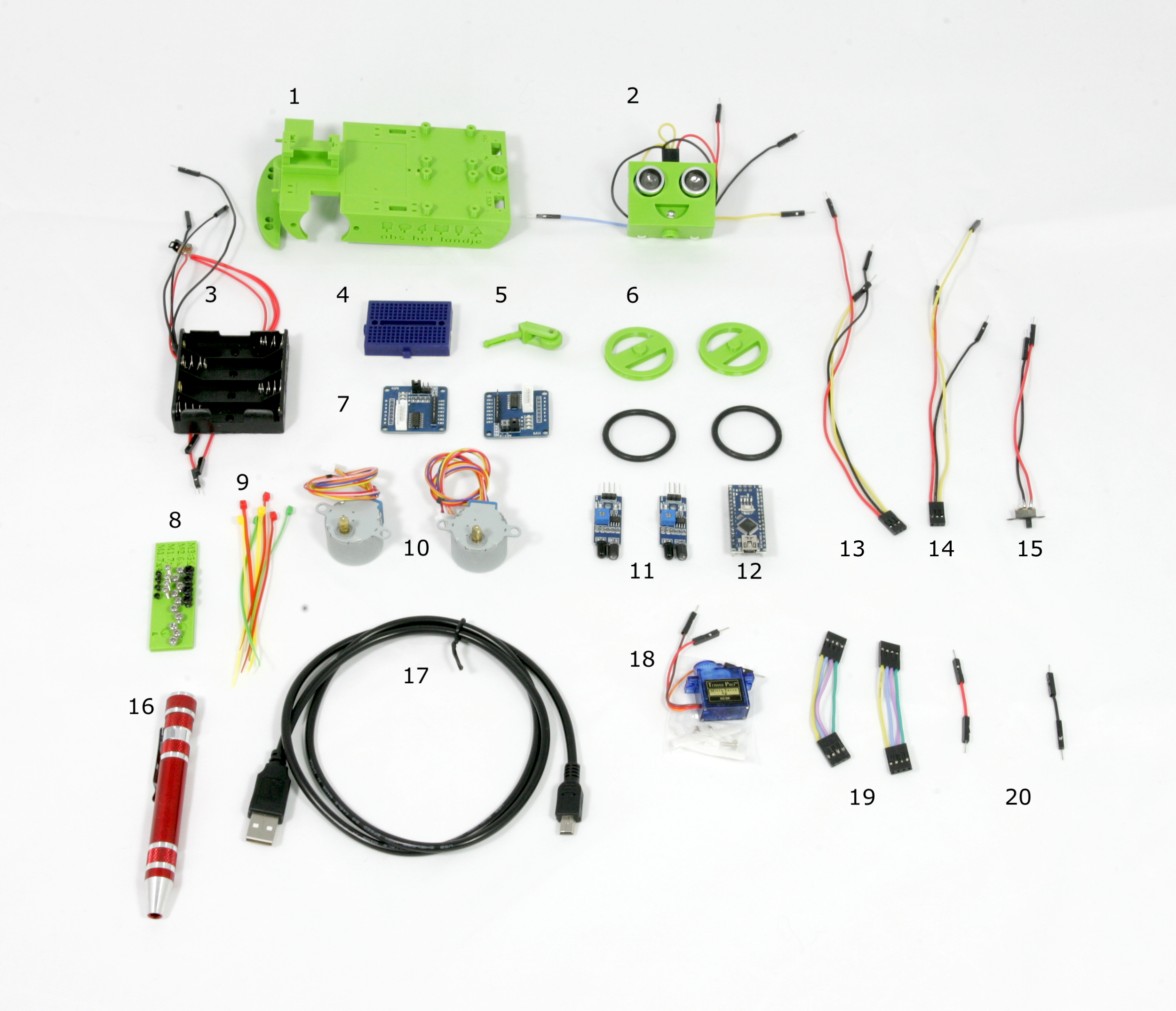
This guide documents the parts and tools to be purchased to create a complete Landje robot kit. Part of the preparation is assembling the wiring looms and preparation of the led and its wiring. If you have completed this guide the kit will reassemble the picture below.
| Qty | Article | Details | Est. price |
|---|---|---|---|
| 4 | Philips head self-tapping micro screws. M3.5x6 |  AliExpress AliExpress |
€ 0,13 |
| 10 | Philips head self-tapping micro screws. M2.6x4 |  AliExpress AliExpress |
€ 0,28 |
| 4 | Philips head self-tapping micro screws. M1.7x8 |  AliExpress AliExpress |
€ 0,14 |
| 4 | !!!!!!!!!!!!!!!! CORRECION Philips head self-tapping micro screws. M1.7x4 | 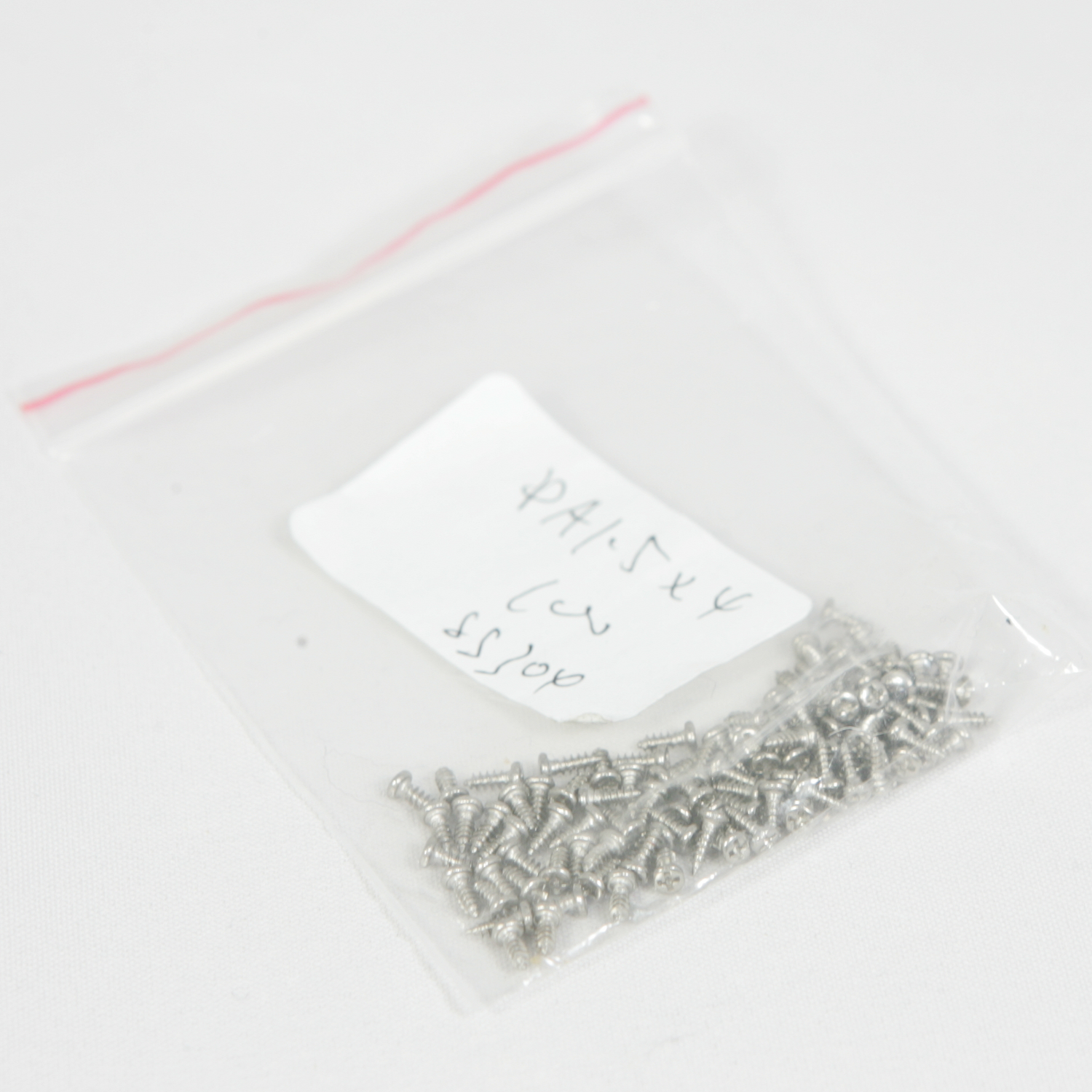 AliExpress AliExpress |
€ 0,12 |
| Qty | Article | Details | Est. price |
|---|---|---|---|
| 1 | Tower pro SG90 RC Micro Servo 9g | 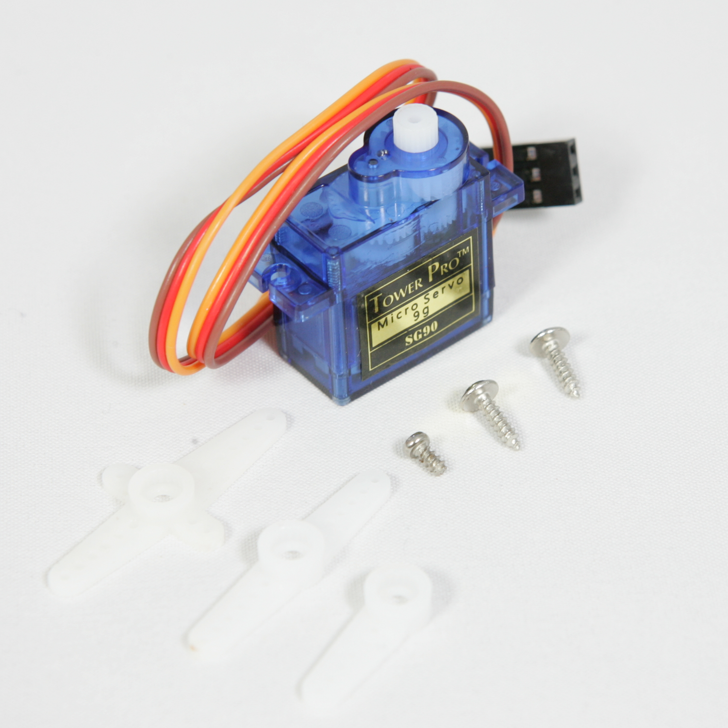 AliExpress AliExpress |
€ 1.05 |
| 1 | Arduino Nano 3.0 CH340 USB driver 16 Mhz | 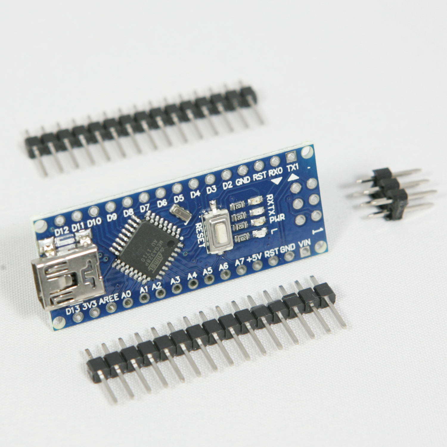 AliExpress AliExpress |
€ 2,00 |
| 2 | ULN2003 Stepper Motor Driver Board SMD | 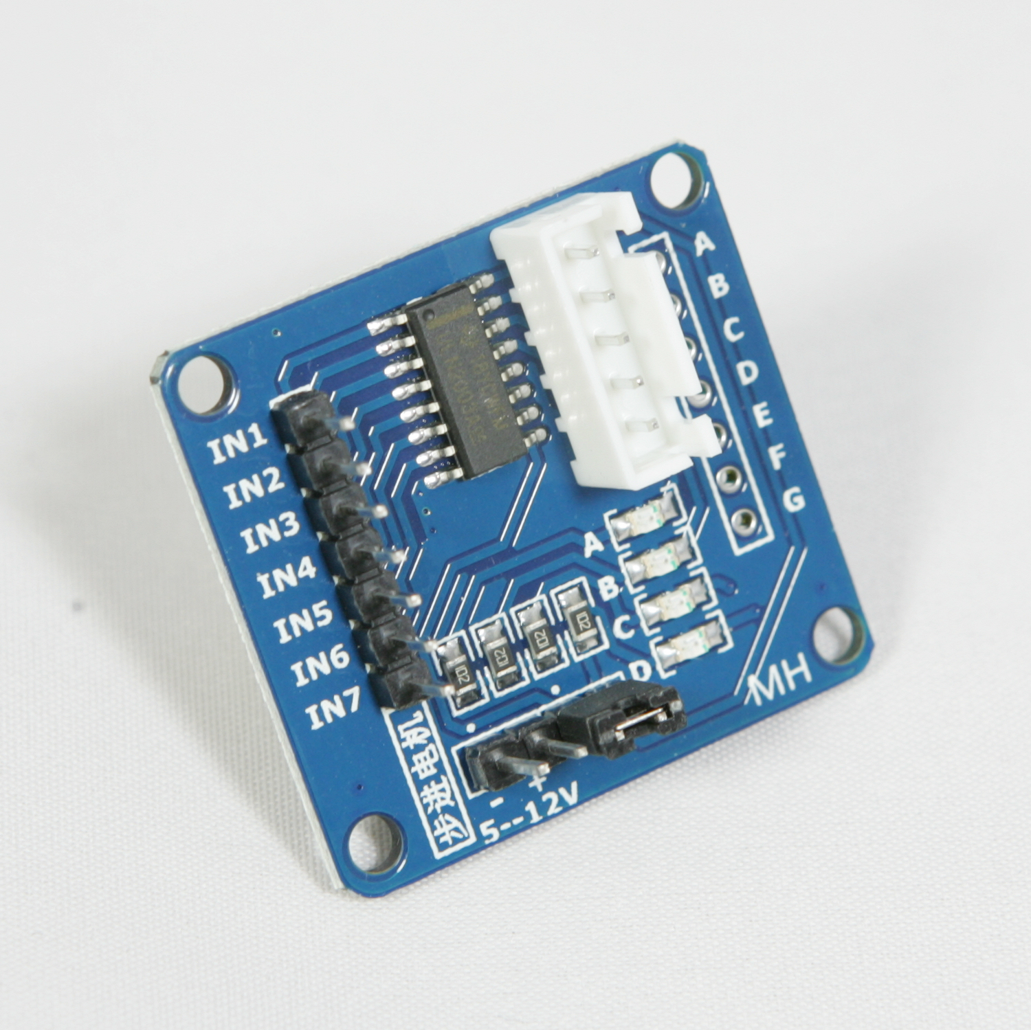 AliExpress AliExpress |
€ 1,16 |
| 2 | 28BYJ-48-5V Stepper motors | 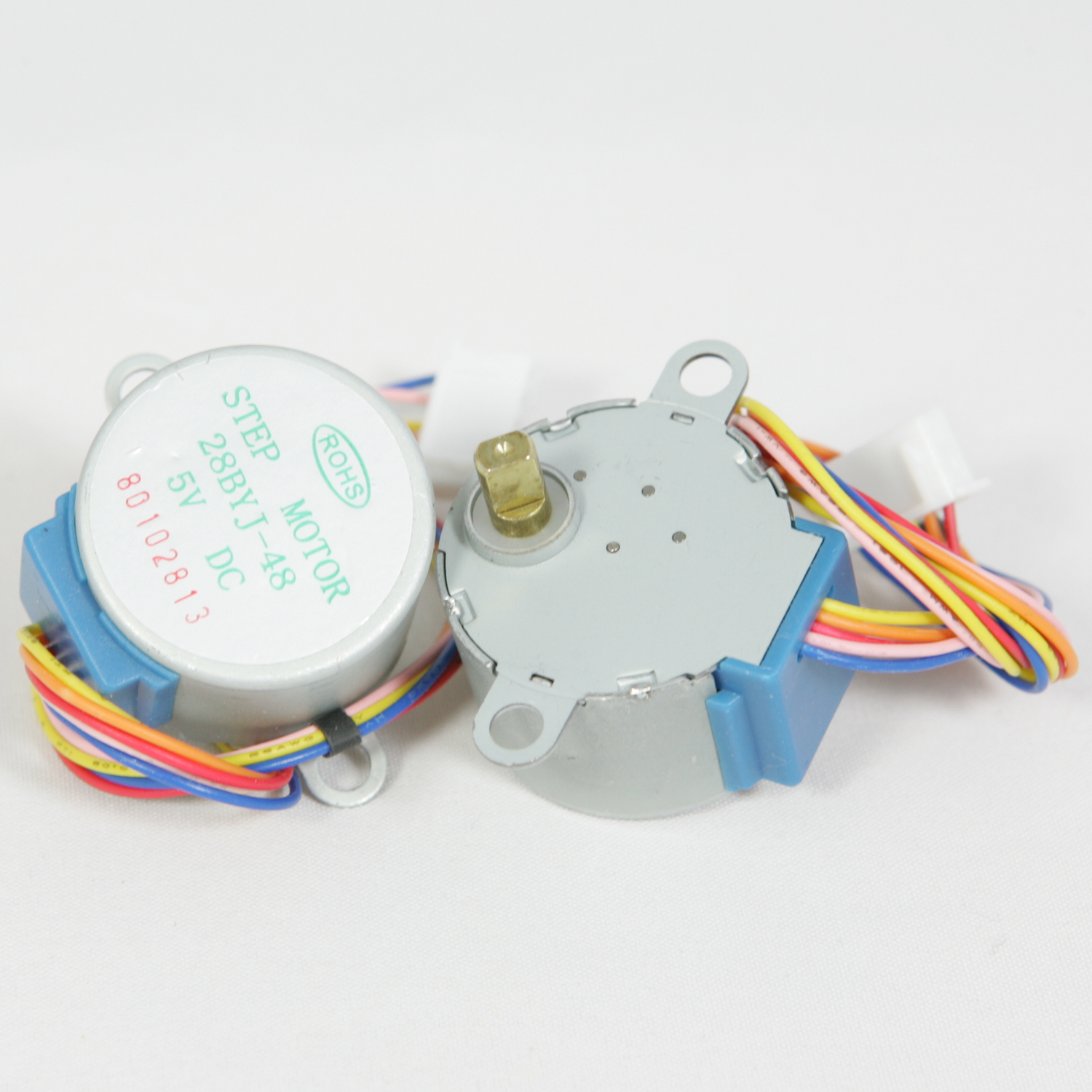 AliExpress AliExpress |
€ 2,28 |
| 1 | AA Power Battery Storage Case Plastic Box Holder With 4 Slots | 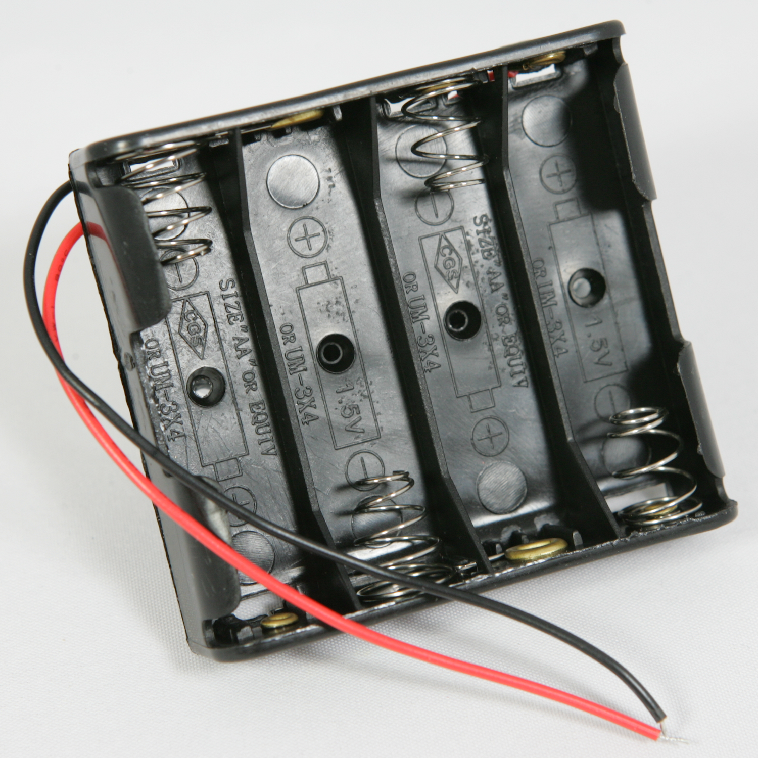 AliExpress AliExpress |
€ 0,40 |
| 1 | 1/6W Metal Film Resistor 220Ω | 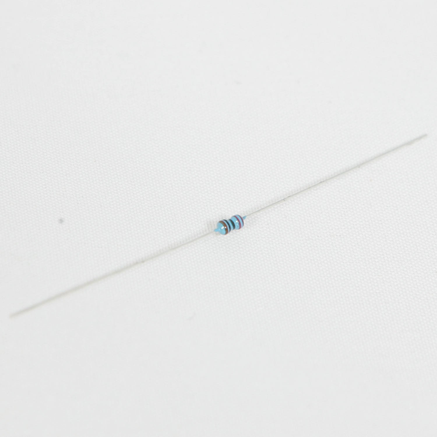 AliExpress AliExpress |
€ 0,01 |
| 2 | IR Infrared Obstacle Avoidance Sensor Module | 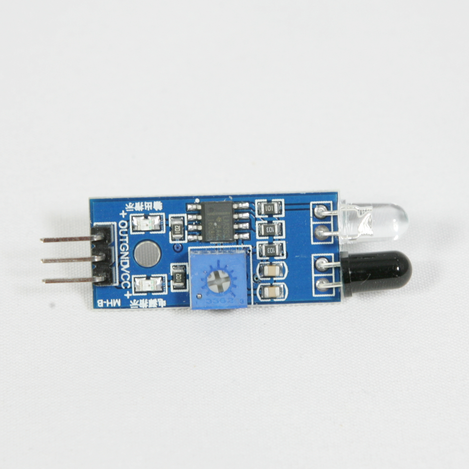 AliExpress AliExpress |
€ 0,90 |
| 1 | SYB-170 Mini Solderless Prototype Breadboard |  AliExpress AliExpress |
€ 0,45 |
| 2 | 5mm Height Knob 3 Pin 2 Position 1P2T SPDT Panel Slide Switch 0.5A | 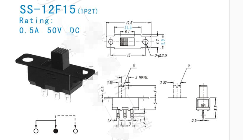 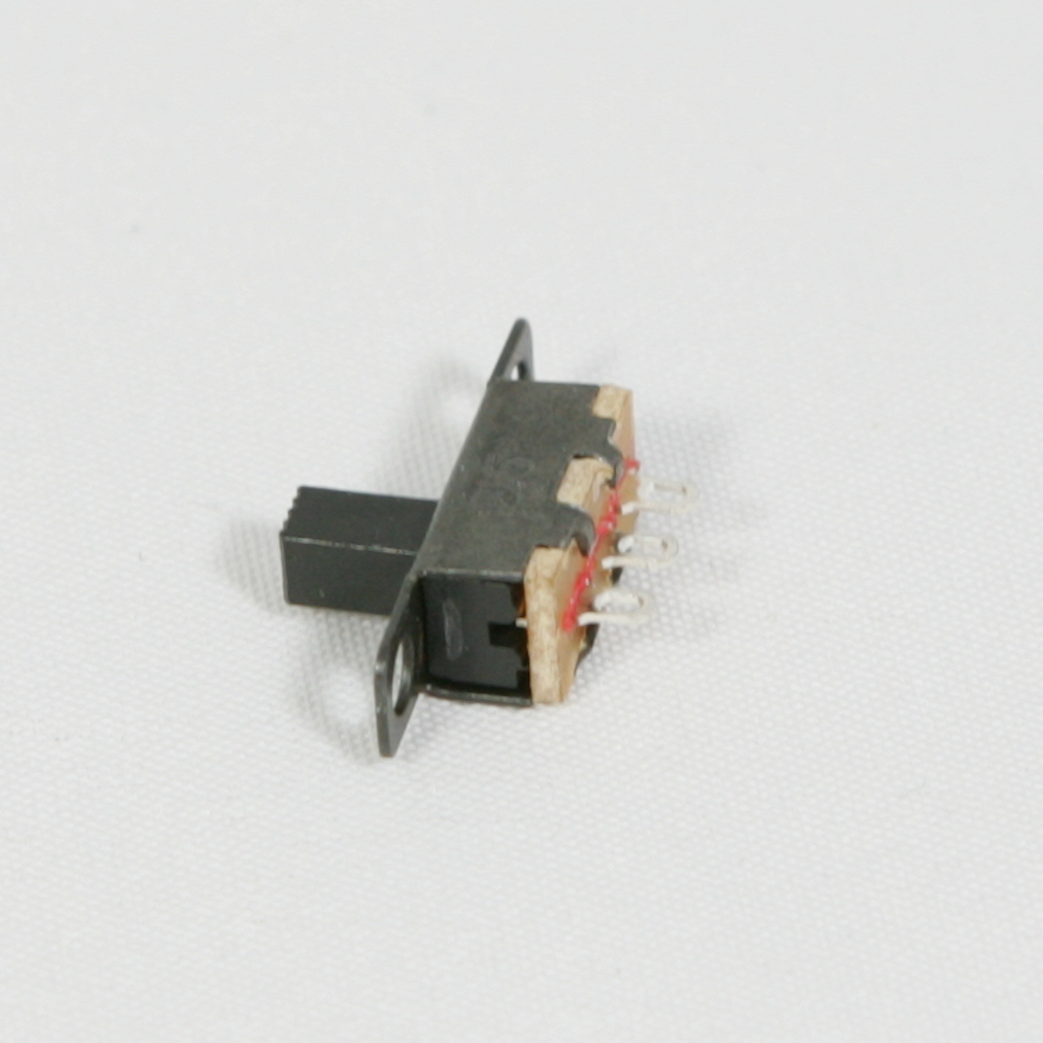 AliExpress AliExpress |
€ 0,16 |
| 2 | Dupont connector 3 pin single row 2.54 mm | 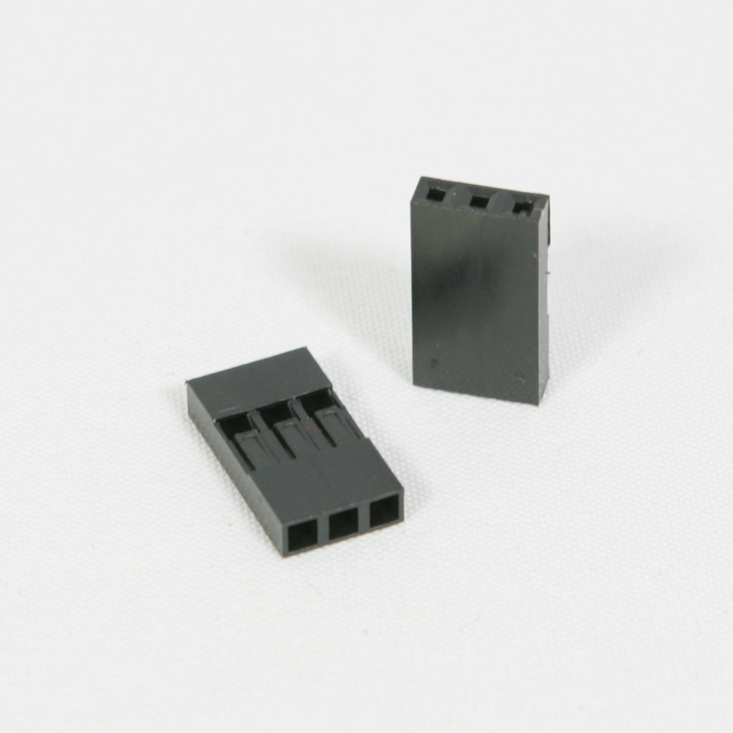 AliExpress AliExpress |
€ 0,03 |
| 5 | Dupont connector 4 pin single row 2.54 mm | 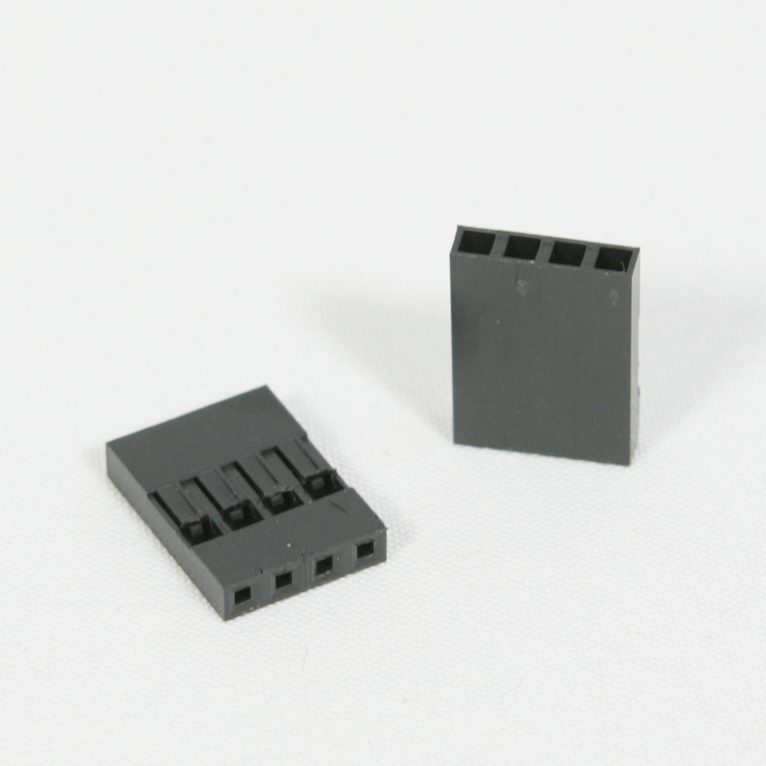 AliExpress AliExpress |
€ 0,08 |
| 26 | Dupont connector 1 pin single row 2.54 mm | 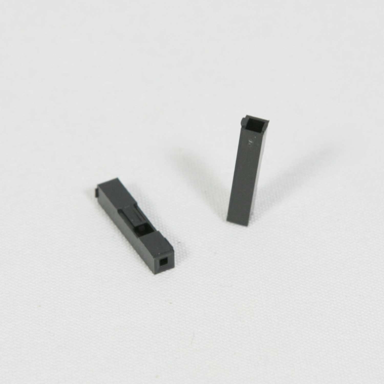 AliExpress AliExpress |
€ 0,31 |
| 22 | Dupont connector reed 2.54 mm metal terminal female | 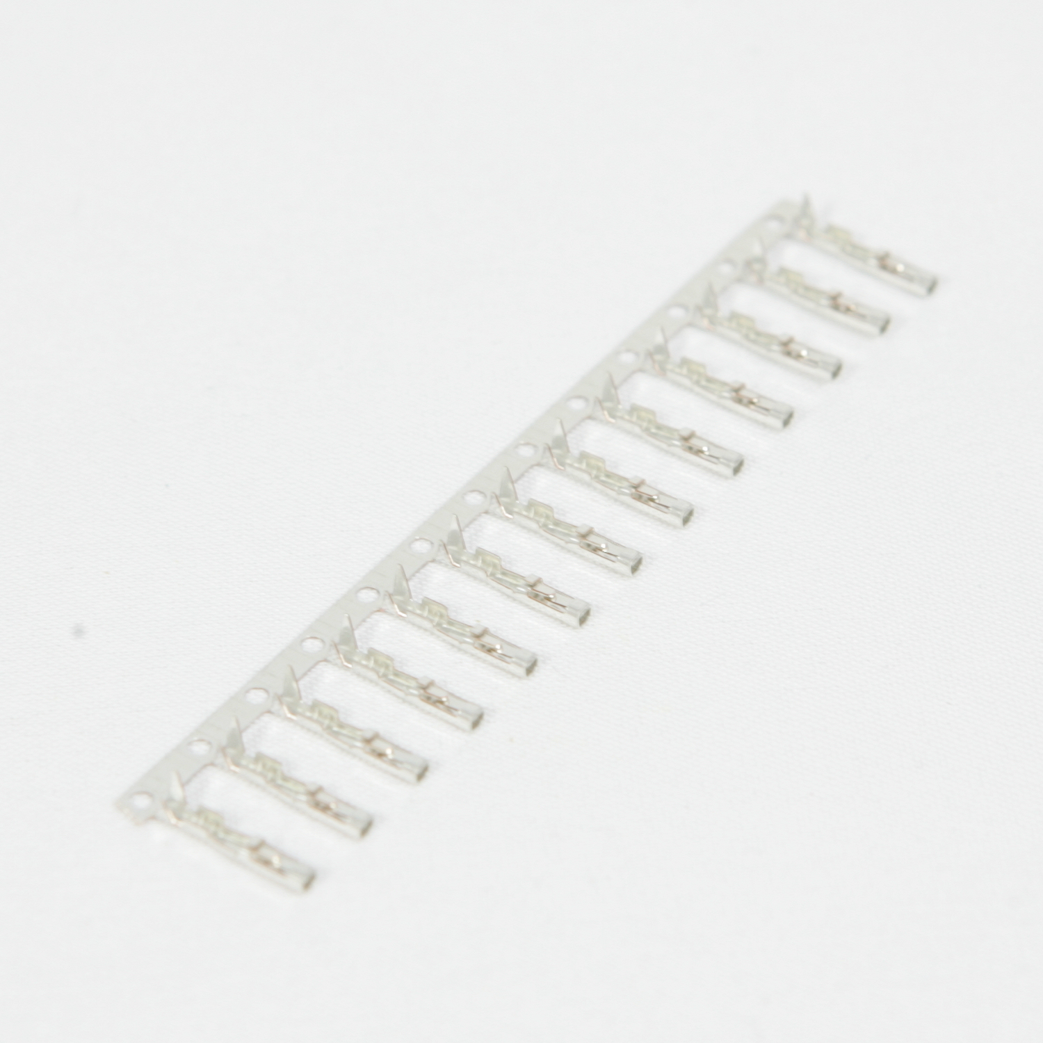 AliExpress AliExpress |
€ 0,30 |
| 29 | Dupont connector reed 2.54 mm metal terminal male | 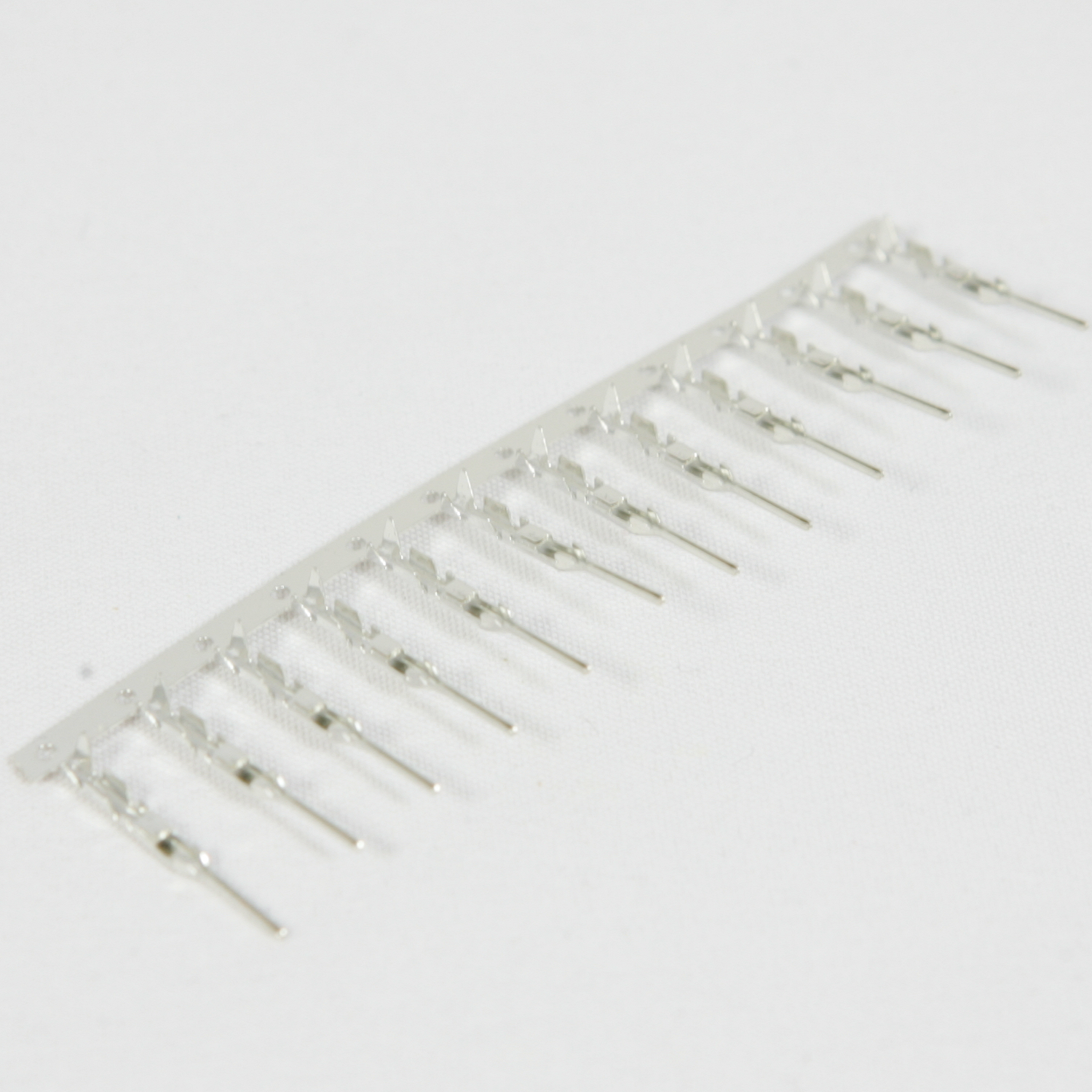 AliExpress AliExpress |
€ 0,50 |
| 6 | Different colors of 26AWG Silicone WireRed, Black, Blue, Green, Yellow, Purple | Buy 2 boxes of Striveday 26AWG Silicone Wire. Sufficient to build a colony of robotsEach robot requires about 1.5m wire.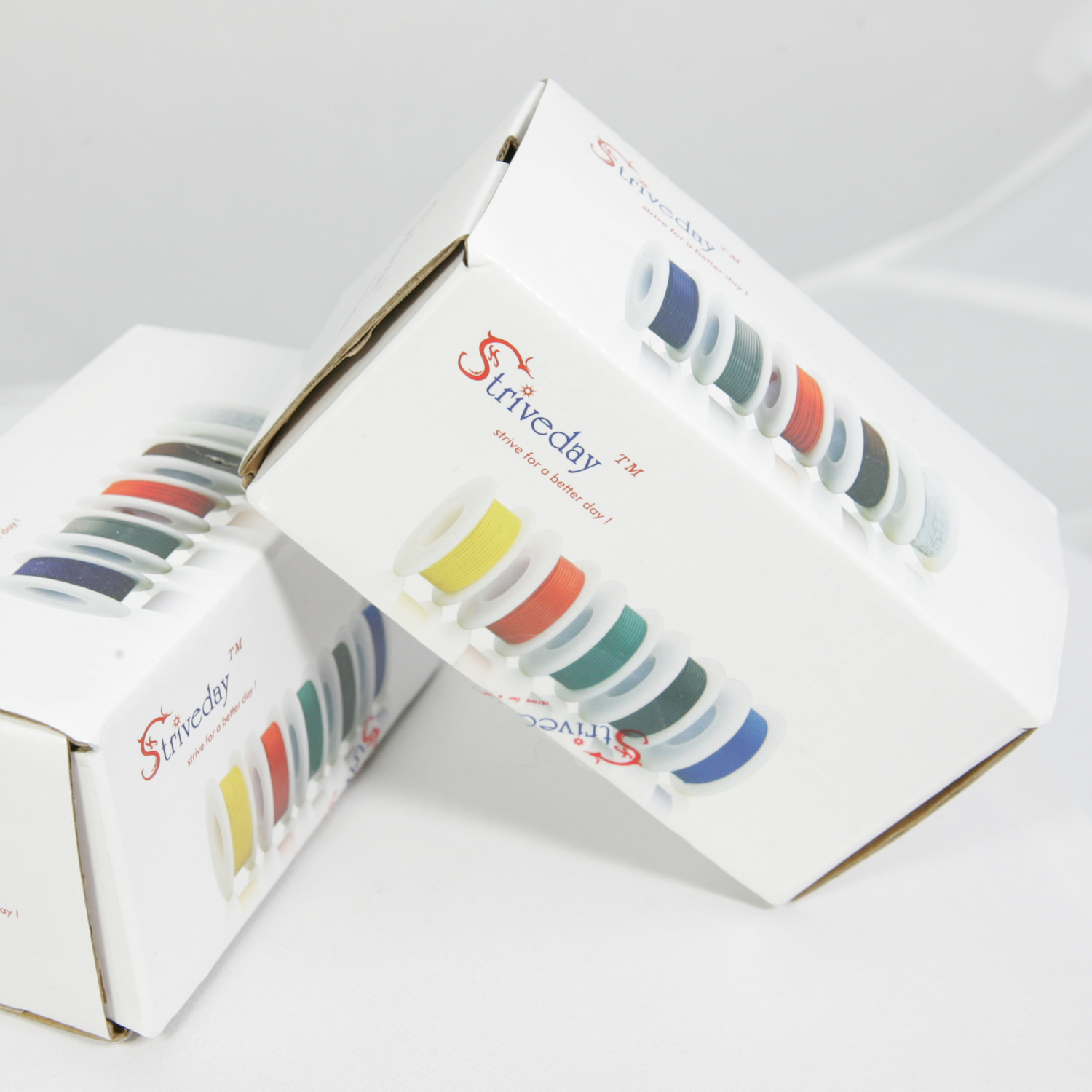 AliExpress AliExpress |
€ 0,50 |
| 1 | Ultrasonic Module HC-SR04Distance Measuring Transducer Sensor | AliExpress | € 0,80 |
| 1 | 5mm(4.8mm) Red straw hat LED | 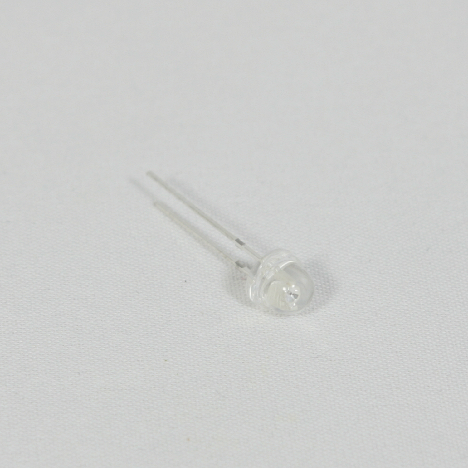 AliExpress AliExpress |
€ 0,02 |
| 1 | USB Cable |
| Qty | Article | Details | Est. price |
|---|---|---|---|
| 2 | O-Ring 36mm | Buy some Plastic Robot Chassis Wheels with Rubber Band and discard the wheel. 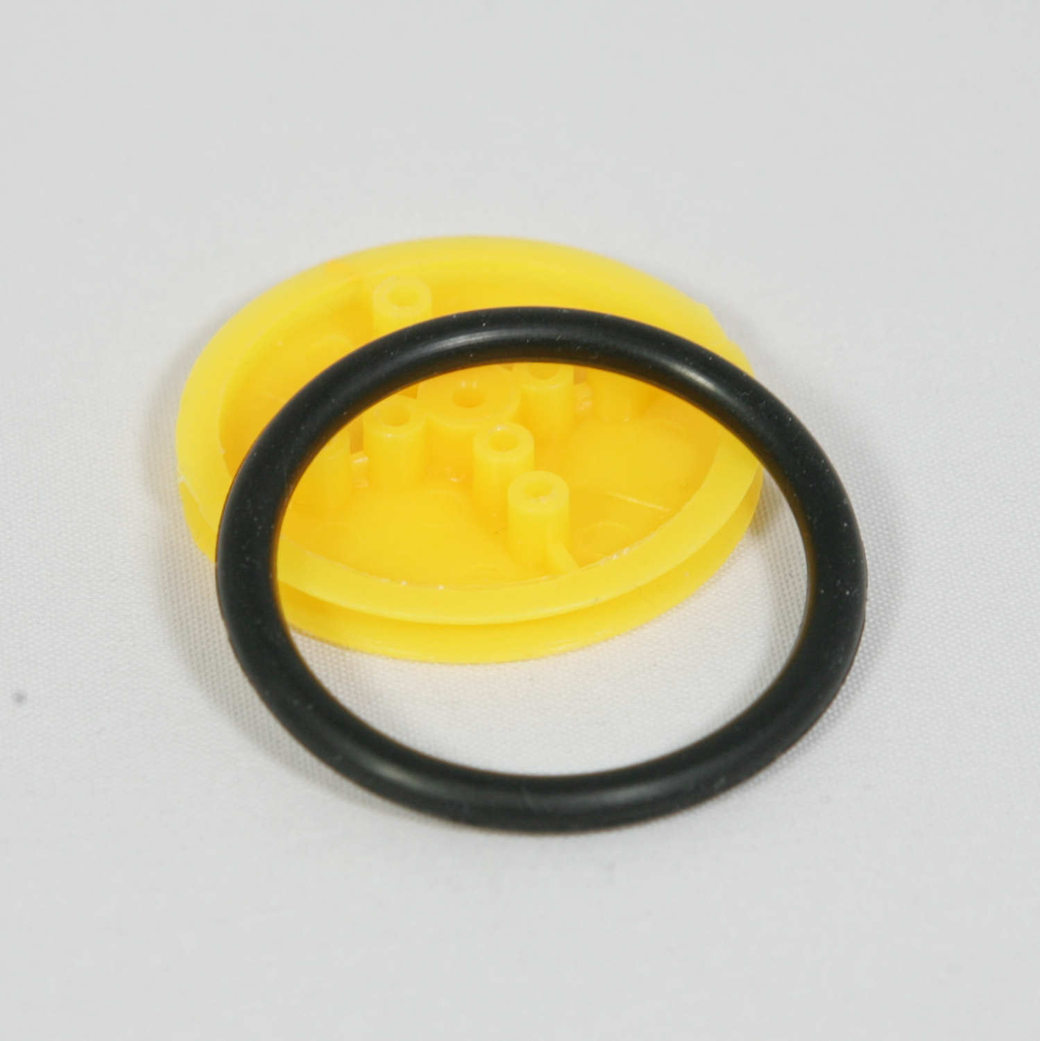 AliExpress AliExpress |
€ 0,59 |
| 1 | 2cm length 4MM heat shrink tube | 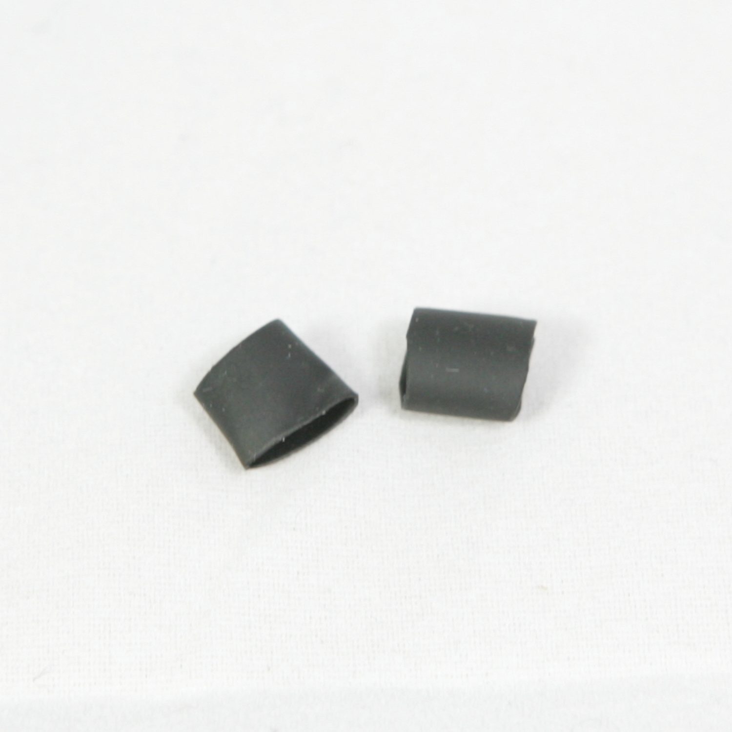 AliExpress AliExpress |
€ 0,01 |
| 8 | 100mm x 2mm wire zip ties | 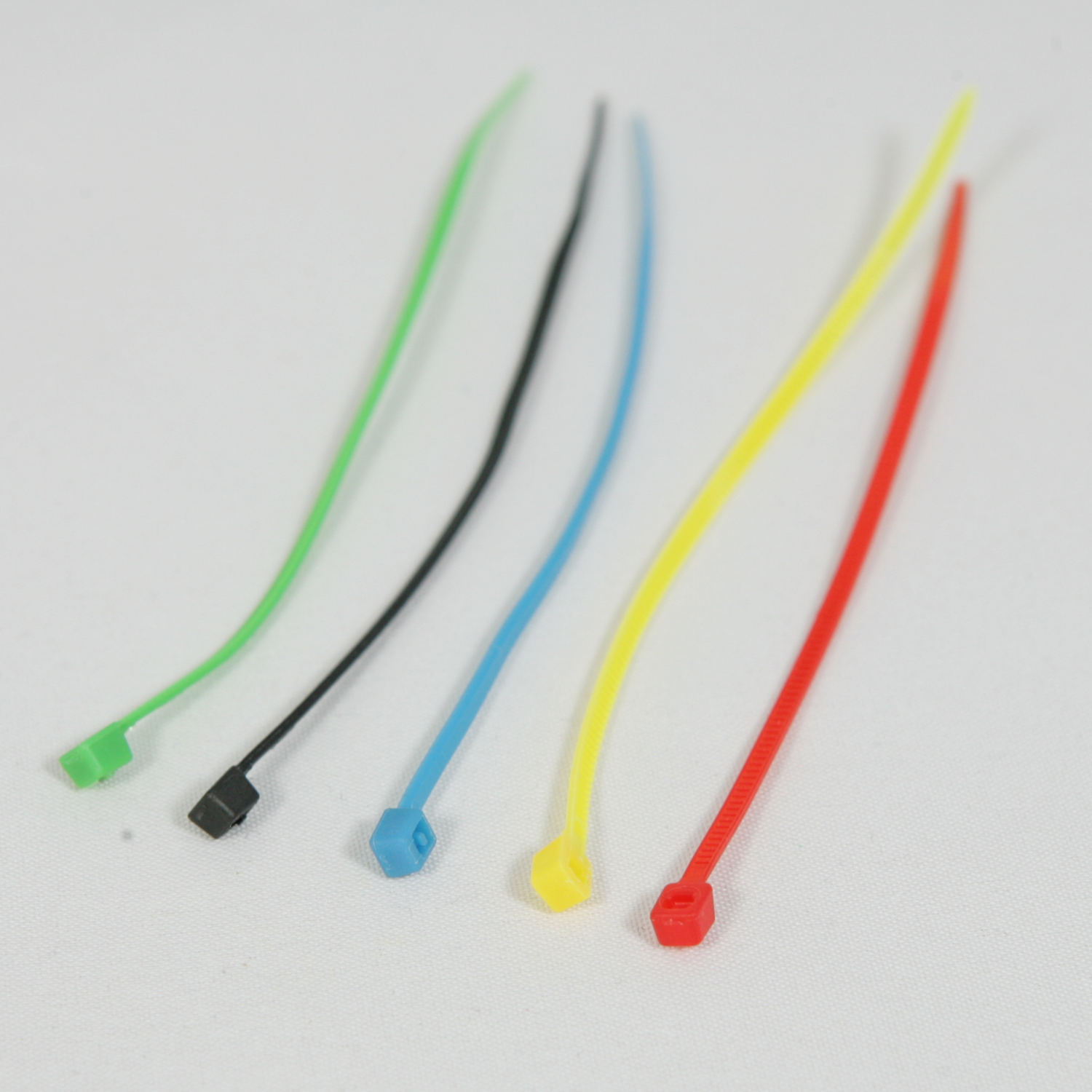 AliExpress AliExpress |
€ 0,11 |
| 1 | 12mmx2mm Stainless Steel Round Rod Axle Bars for RC Toys | 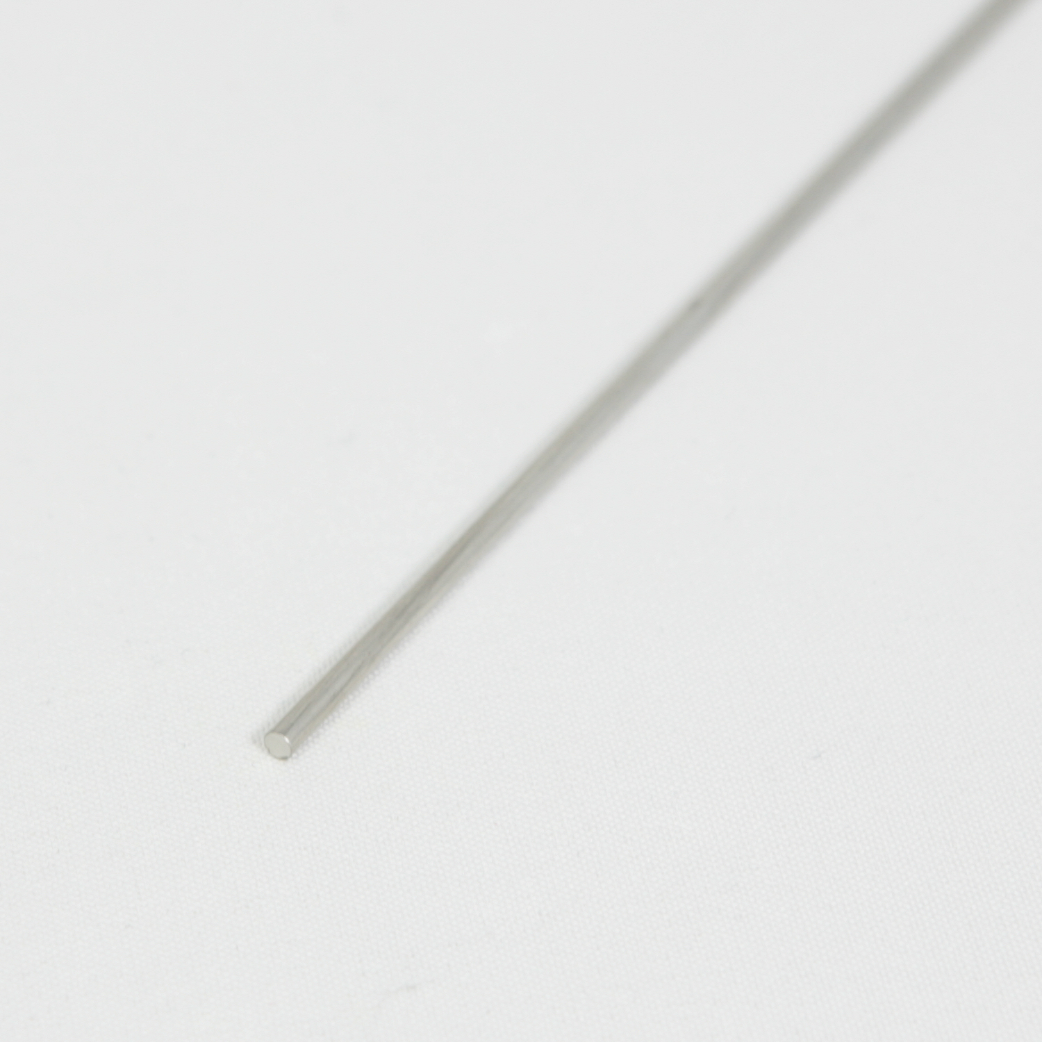 AliExpress AliExpress |
€ 0,01 |
I developed the 3D printed parts using Tinkercad and an Ultimaker 3 printer. Because results of the printed parts may slightly differ per printer and the used parts may change over time you may need to adopt the design of the parts. Therefore the designs are freely available on Tinkercad in the project TinkercadProjectName. The STL files can be directly downloaded from the STL folder in the Github repository. An optimal Curaprofile can be dowloaded also from the UM3 folder when printing on an UM3 with PLA and PVA as support material.
| Qty | Article | Details | Est. price |
|---|---|---|---|
| 1 | Frame | 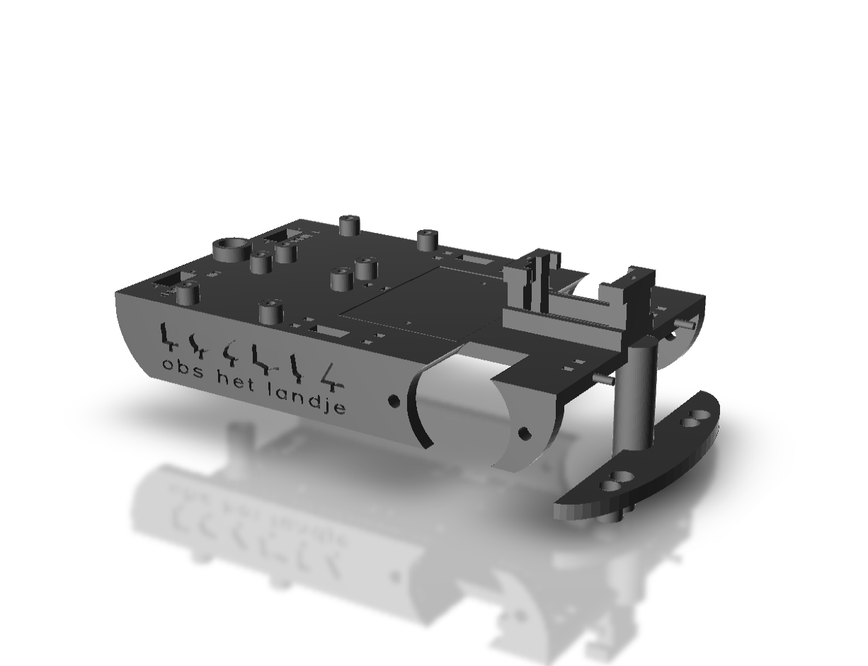 Requires about 77g PLA and 86g PVA Requires about 77g PLA and 86g PVA |
€ 16,03 |
| 1 | Head | 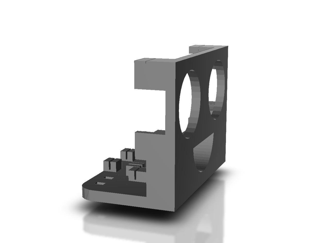 Requires about 14g PLA and 13g PVA Requires about 14g PLA and 13g PVA |
€ 2,69 |
| 2 | Wheel | 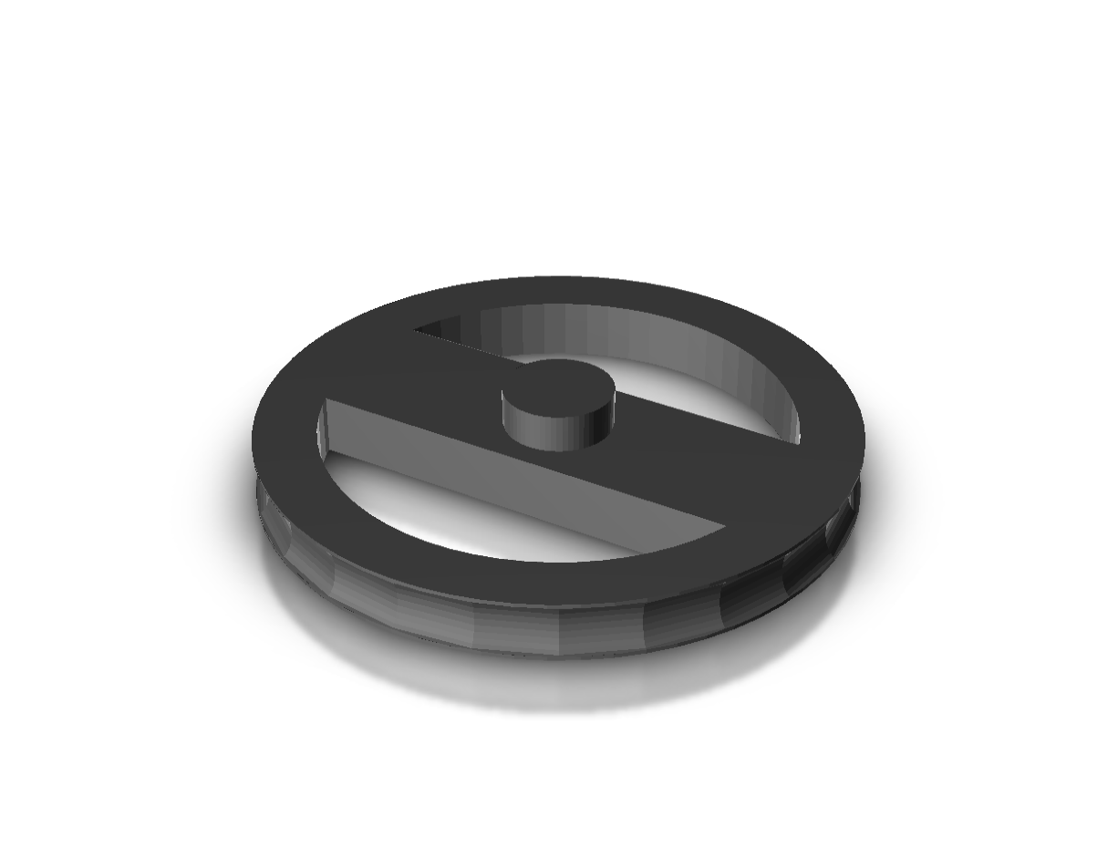 Requires about 6g PLA and 2g PVA Requires about 6g PLA and 2g PVA |
€ 0,72 |
| 1 | Tail wheel | 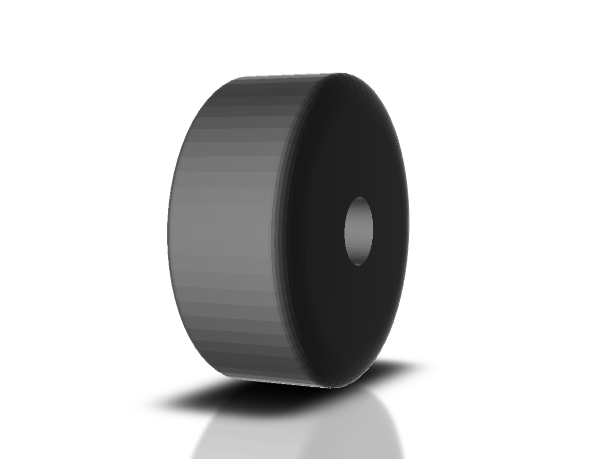 Requires about <1g PLA and 0g PVA Requires about <1g PLA and 0g PVA |
€ 0,07 |
| 1 | Tail wheel steering arm | 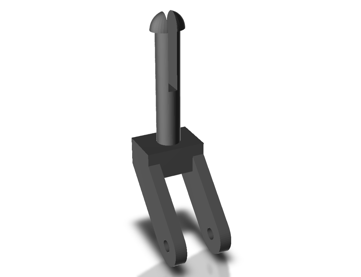 Requires about <1g PLA and 0g PVA Requires about <1g PLA and 0g PVA |
€ 0,07 |
| 1 | Screw organizer | 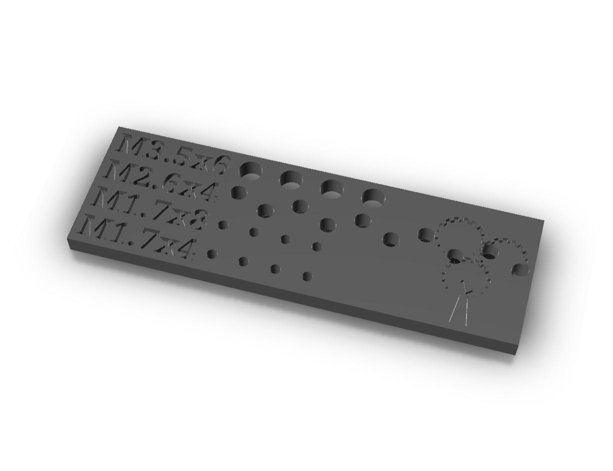 Requires about 3g PLA and 0g PVA Requires about 3g PLA and 0g PVA |
€ 0,24 |
| Qty | Article | Details | Est. price |
|---|---|---|---|
| 1 | PH00 1.5 | Philips PH00 1.5 screwdriver | € |
| 1 | PH1 | Philips PH1 screwdriver | € |
For the kit preparation some more and some less general available tools are required
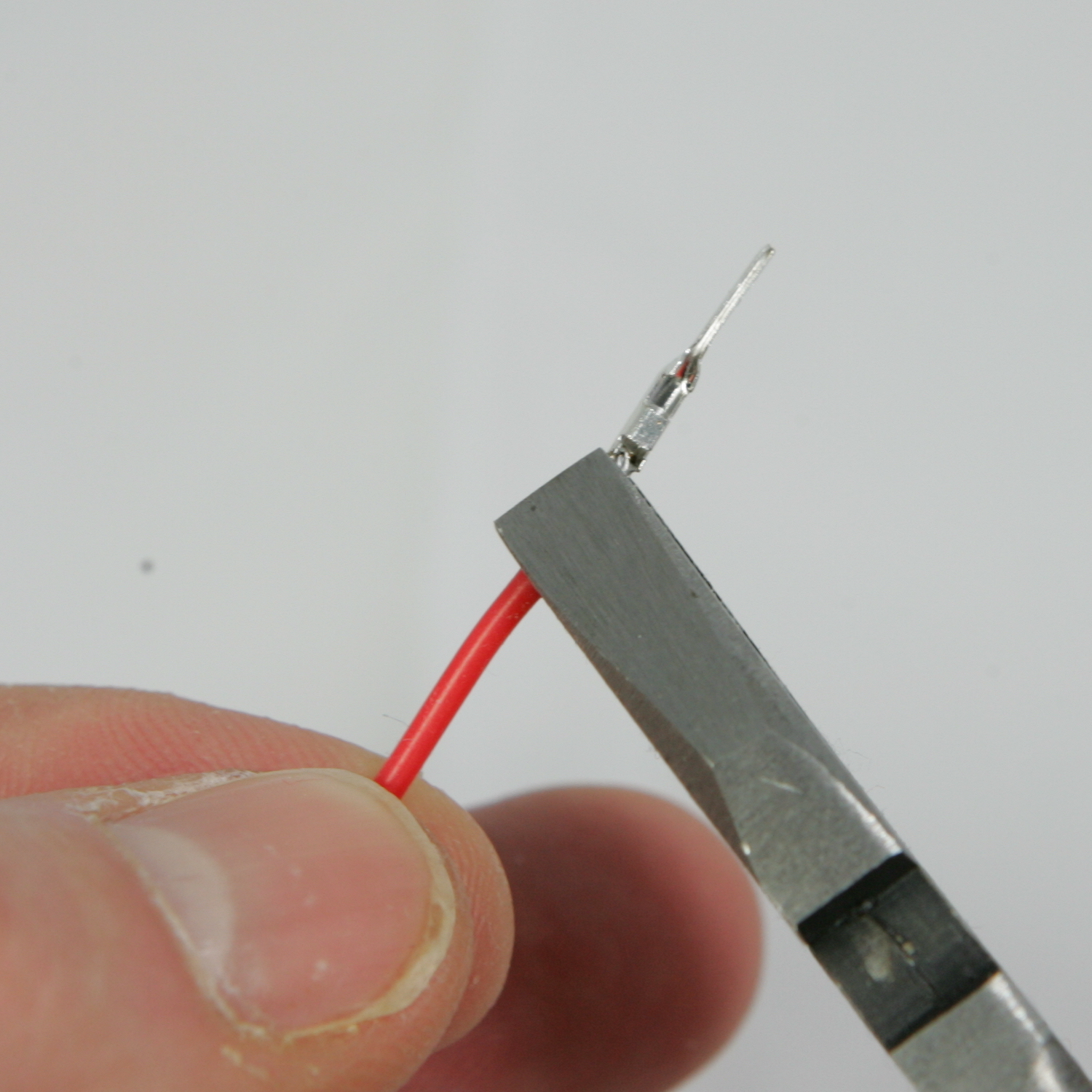
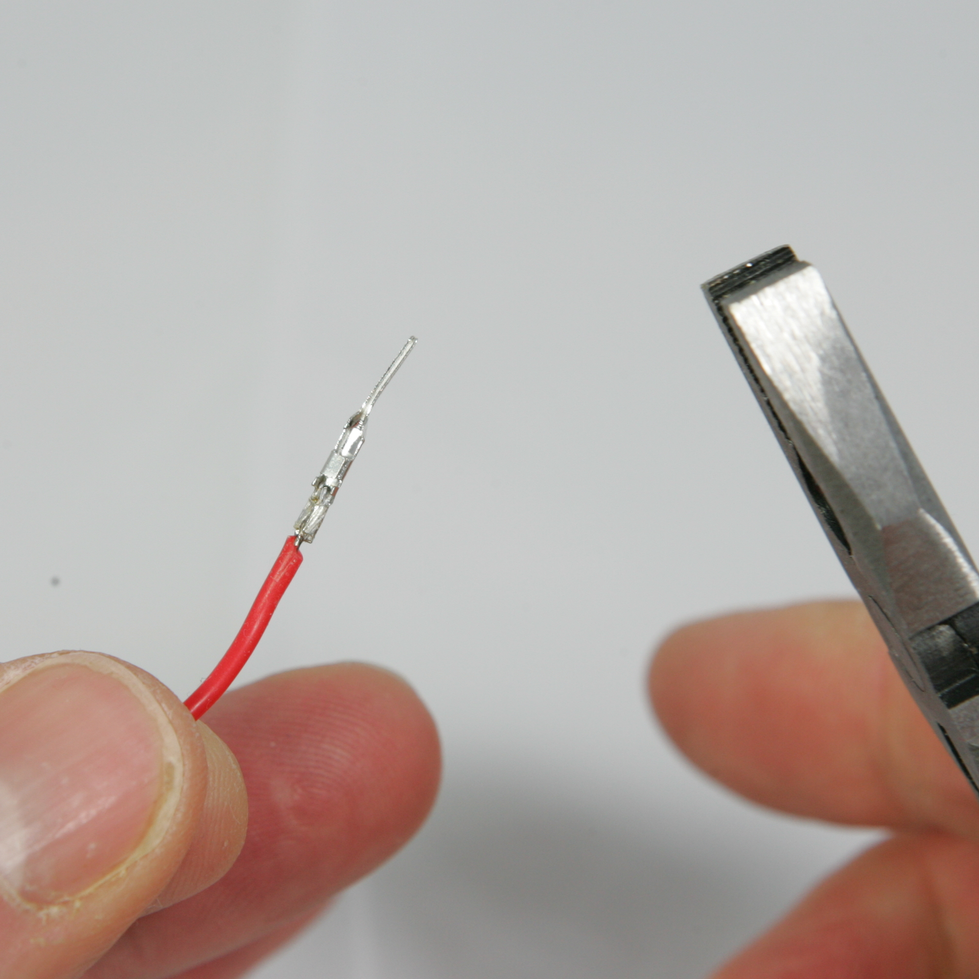
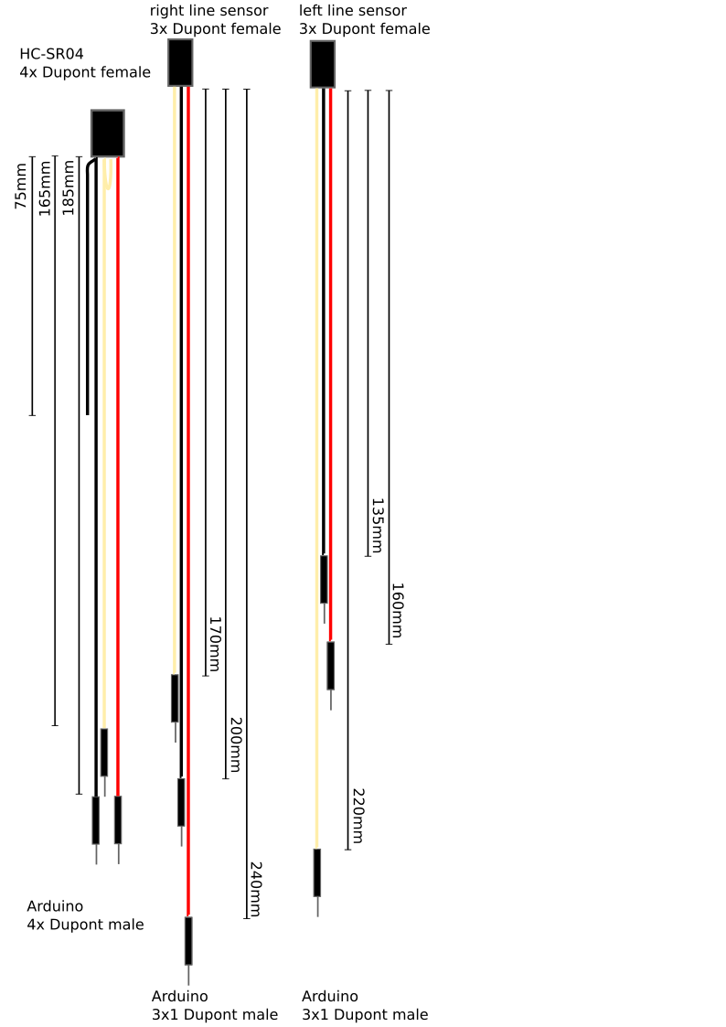
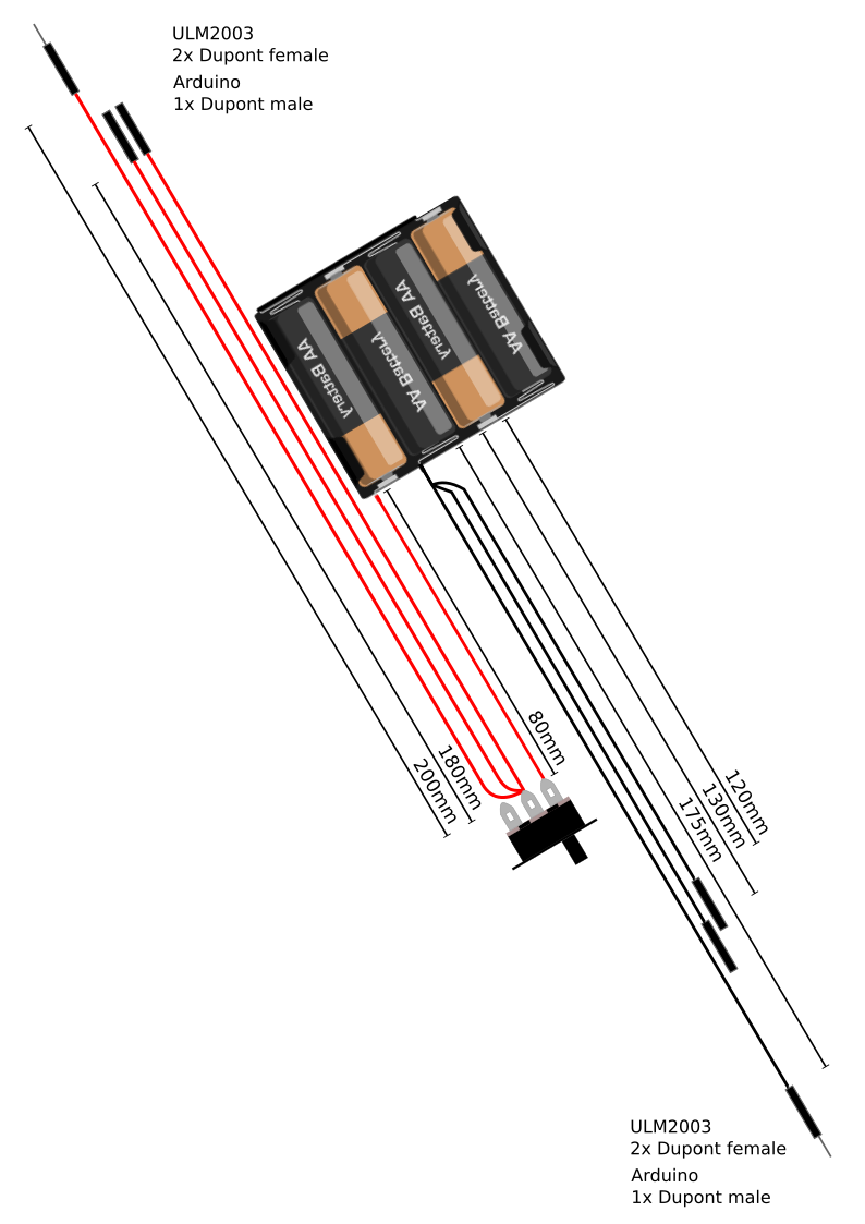
In the next images all wiring looms which need to be assembled are documented. I do personally have bad experience with Dupont crimping pliers and prefer to solder to wires to the Dupont connectors. Soldering, although it requires a steady hand, is not heard and needs a little bit of practice.
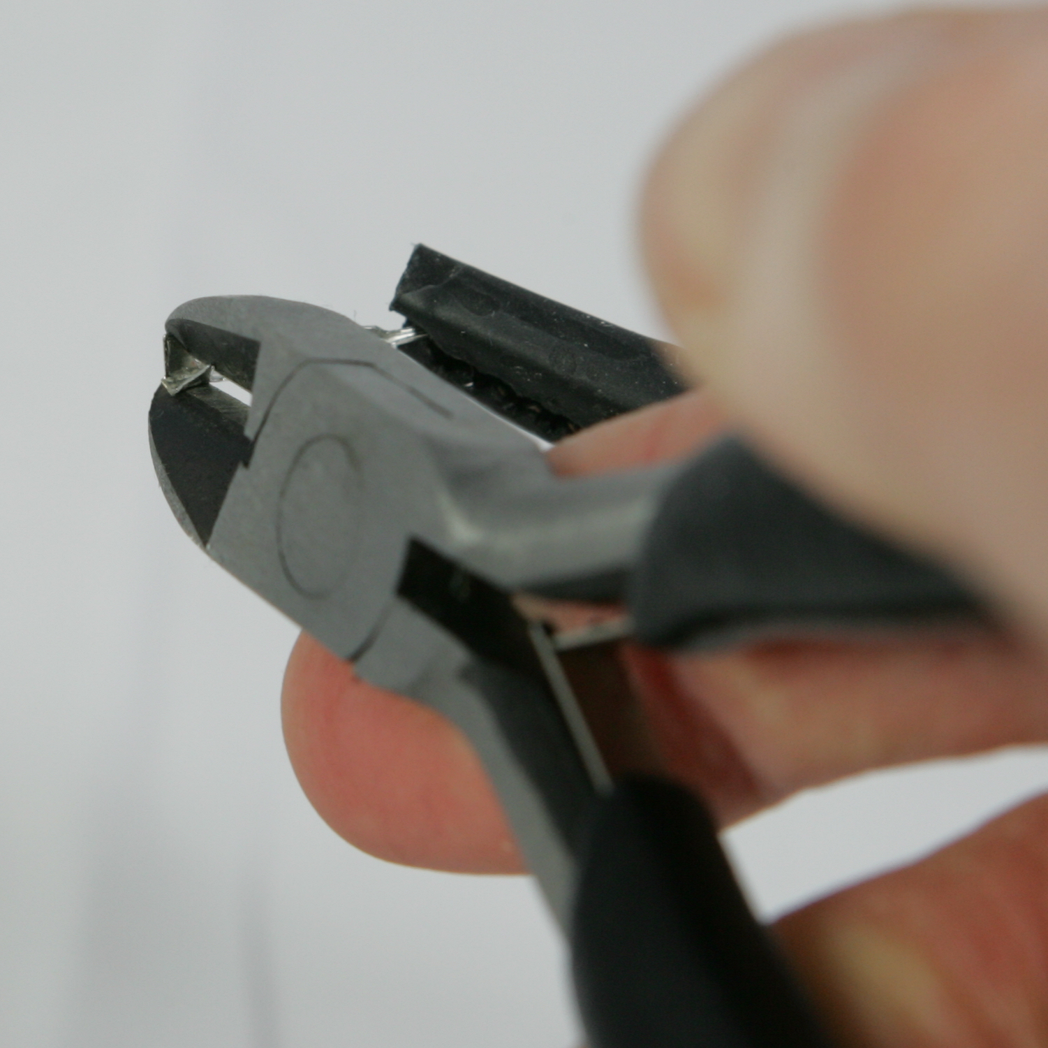
Cut of the fold-over wings
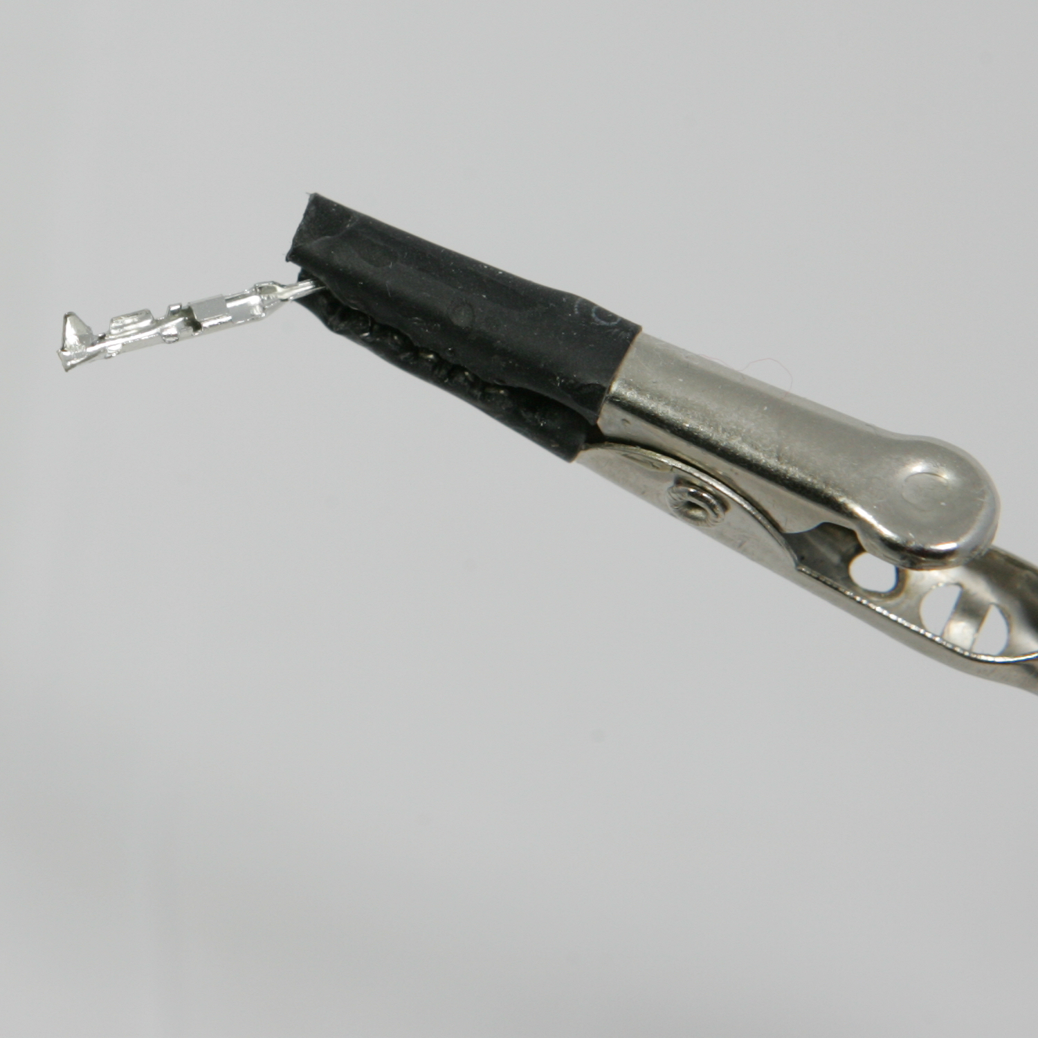
Strip the cable-end about 2mm and tin it
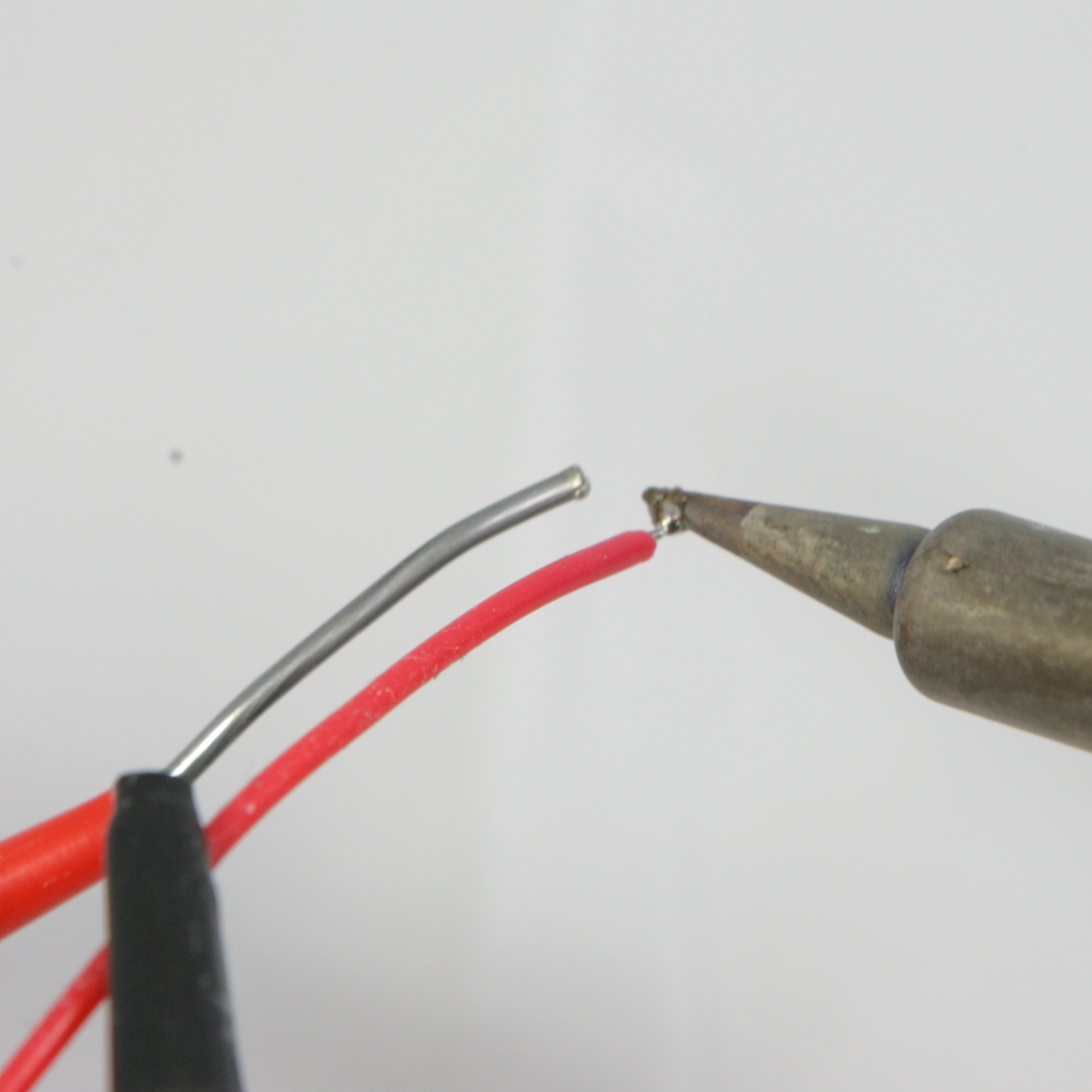
Tin the Dupont connector
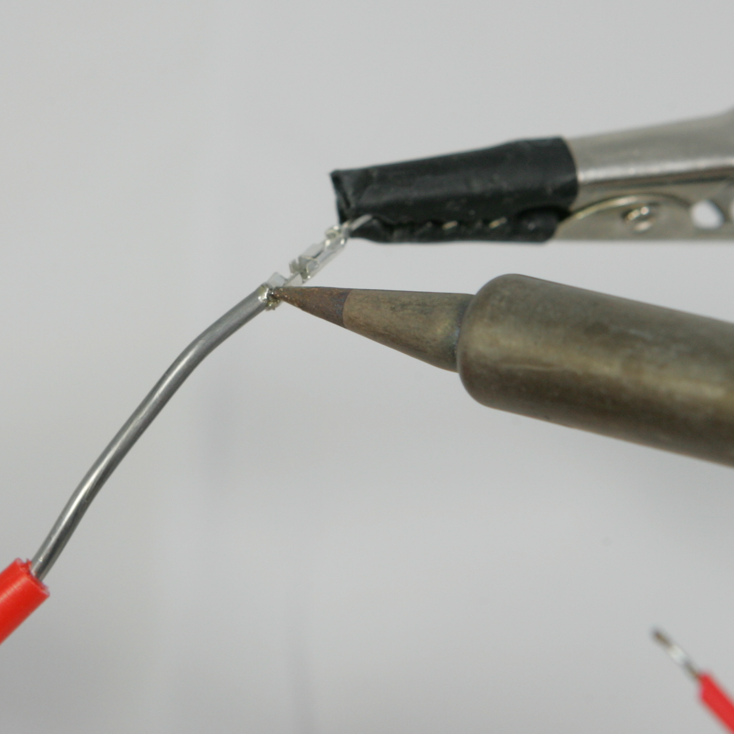
Solder the wire to the connector.
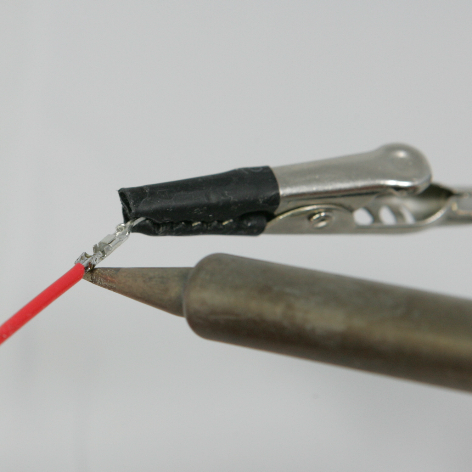
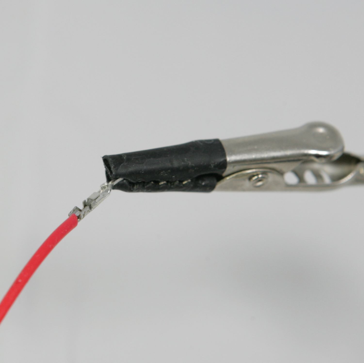
Fold the wings over the wire using a combination or radio plier
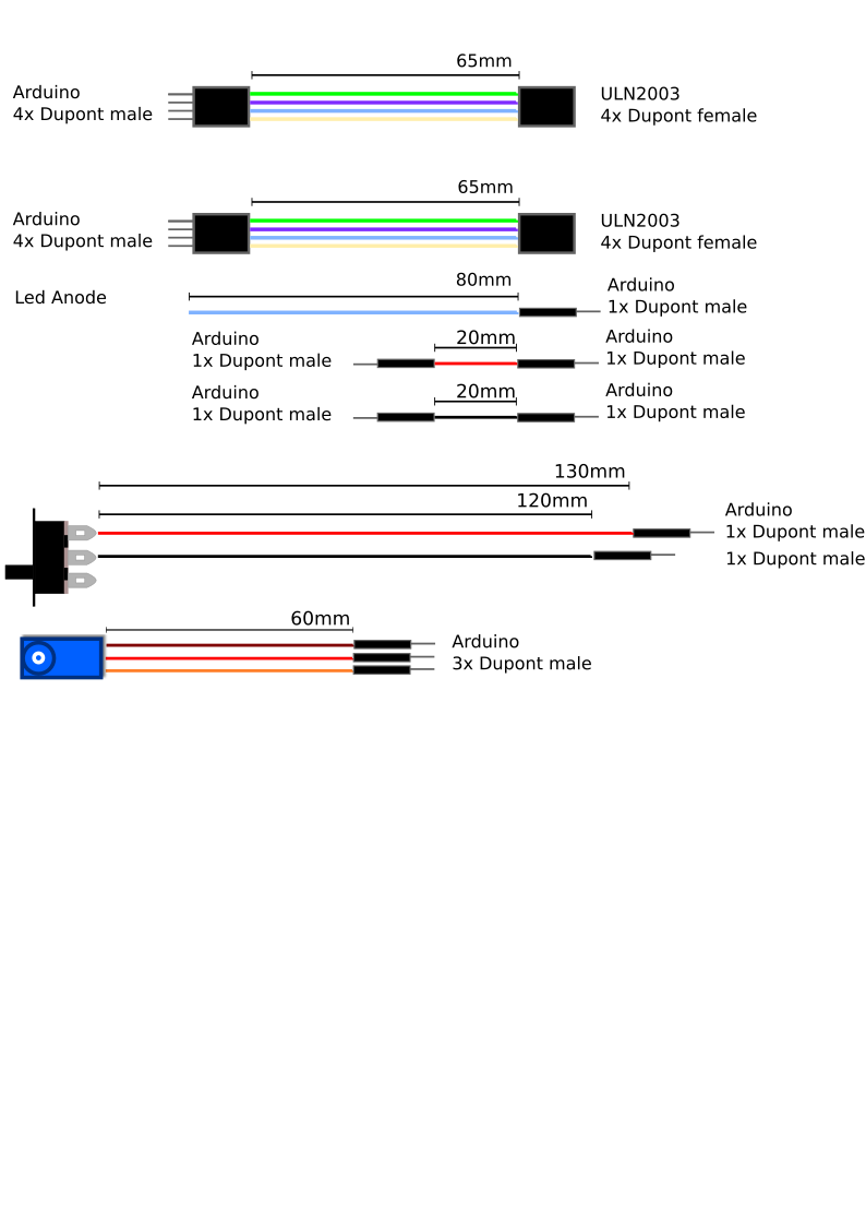
Create the wiring looms shown below. Please be aware that the images may not scale right. If you want to print them on the right scale, download the file wiring diagram.svg and use Inkscape to open and print the file without borders (no-slug). Alternatively you can download the “wiring diagram_*.png” files from the Landje robot Kit preparation folder and print the files border-less (no-slug) on A4 paper.
Servo wires Servos by default have a 3-pin female dupont connector. Cut the servo cable to the desired length and replace the 3-pin female dupont connector by 3 1-pin male dupont
Depending on the (motoric) skills of the students, you can prepare the robot head or let the students assemble and solder the parts themselves. For 8th grade primary school students i did the preparation.
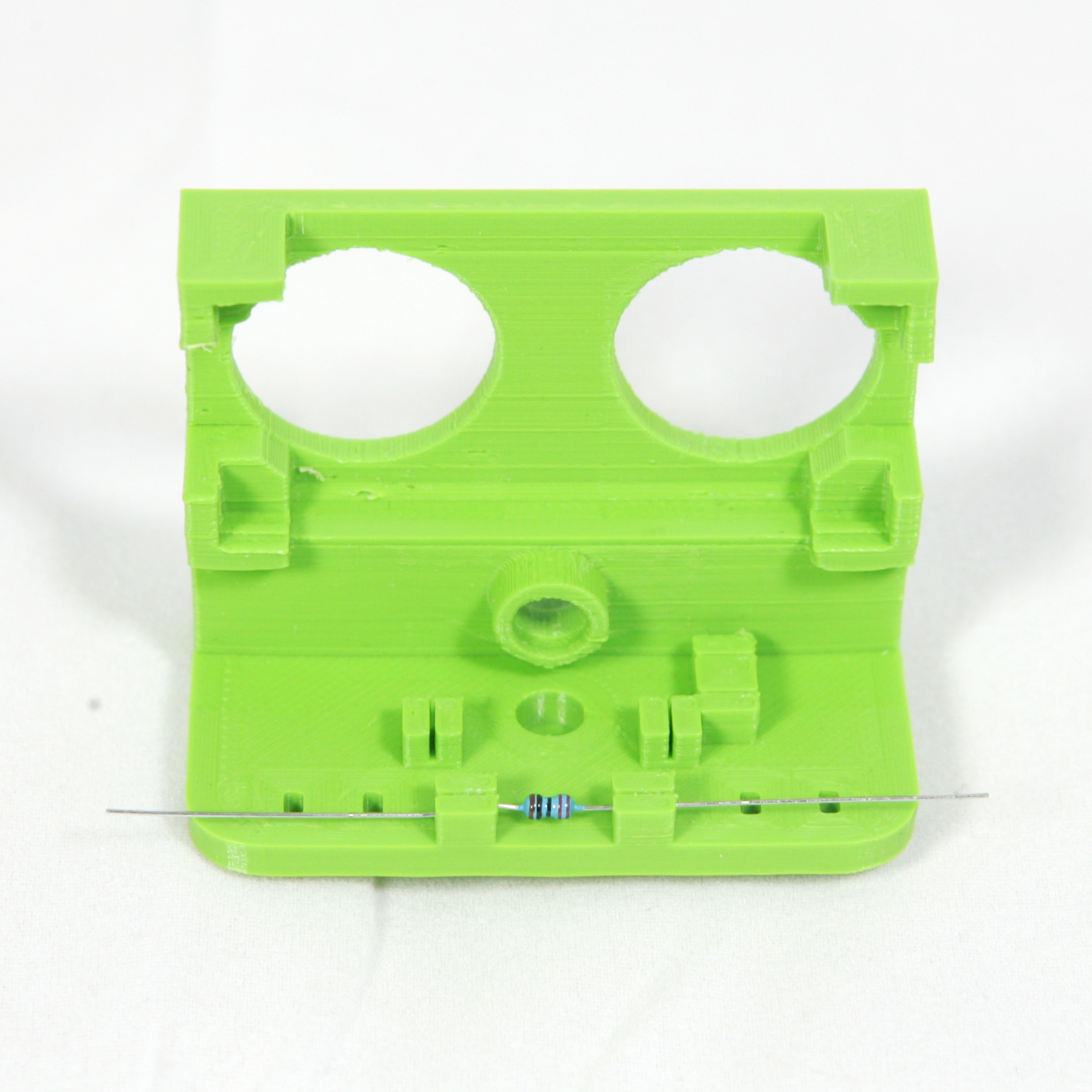
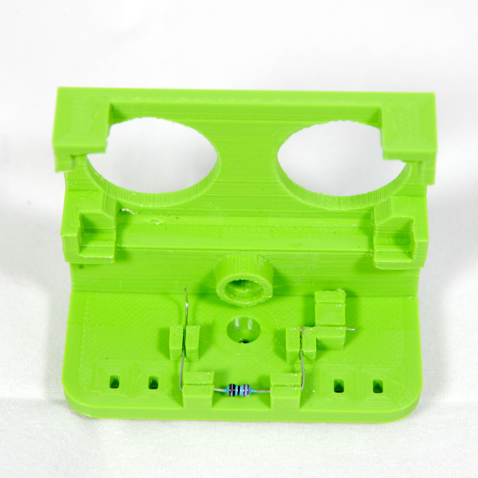
First gather the necessary parts to assemble the robot head.
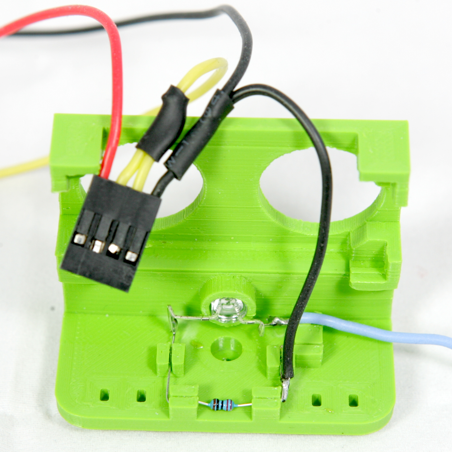
Hold the 3d printed head so the back faces towards you.
Push the resistor in the outer brackets.
Bend both end of the resistor wires 90º and push the wires in the center brackets.
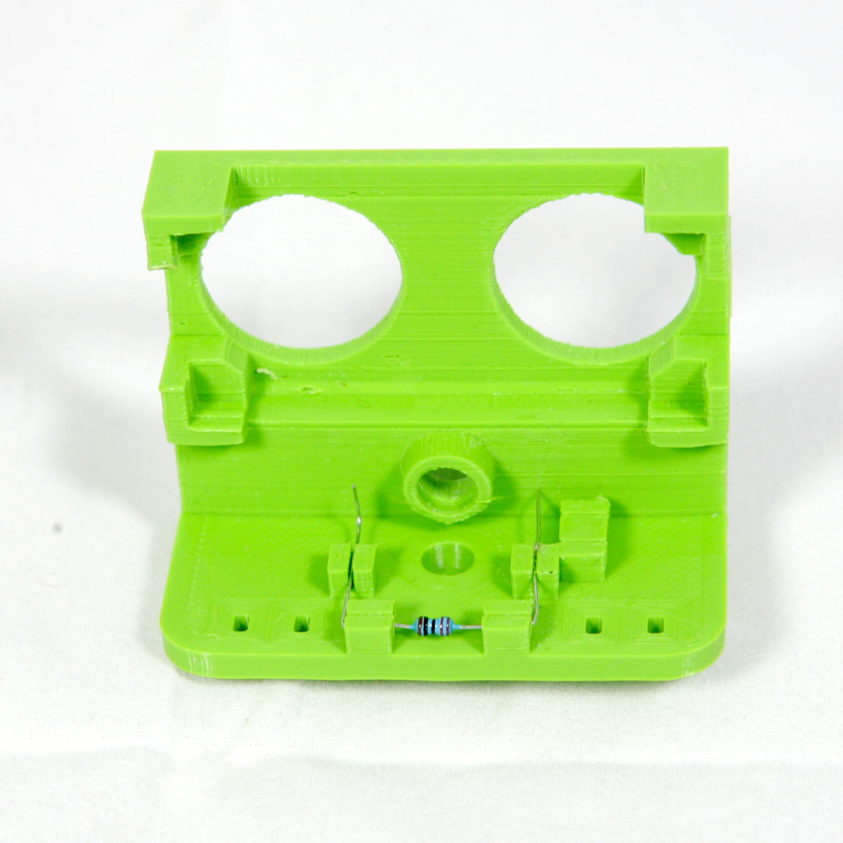
Bend the right wire of the resistor 90º and push it in the right middle bracket.
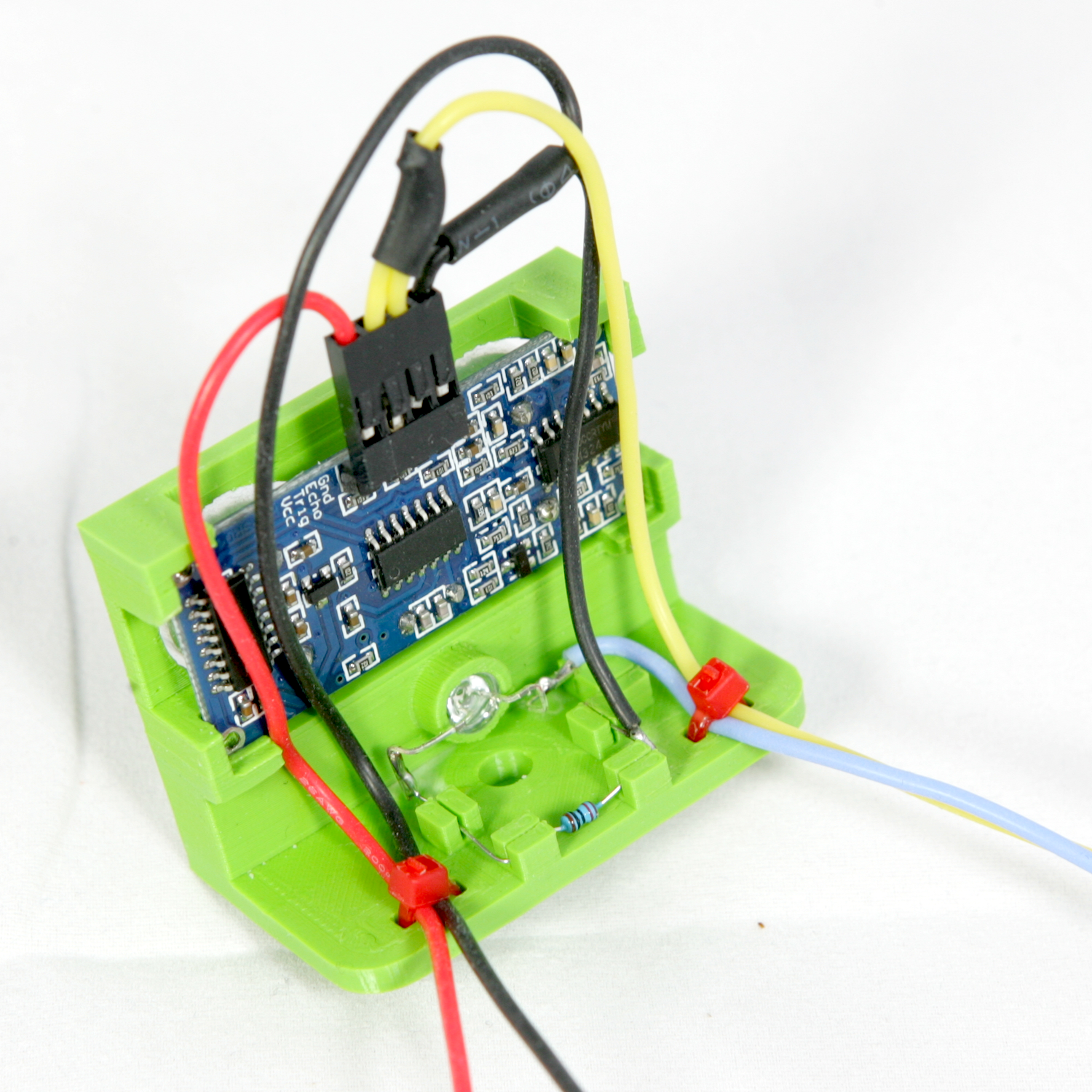
Place the led into the recess. Make sure the kathode, the shorter pin, is on your left. Push the led into the recess of the mouth until it clicks. If you need to apply to much pressure, slightly warm the head using a hot airgun. Make sure no to heat it to much to prevent deformation. When printed in PLA a temperature of 35 degrees is sufficient to soften the plastic.
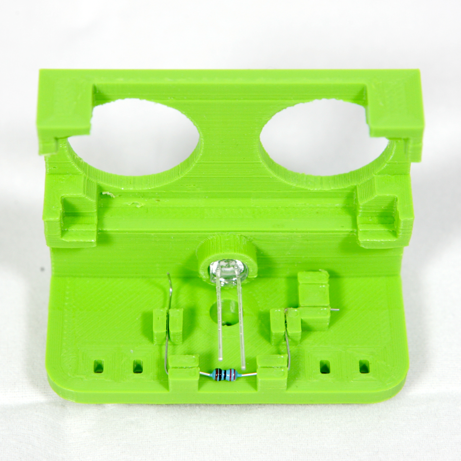
Take the led bend both wires 90º, then make two bends 90º in the left wire till it connects to the resistor. Make three 90º bends in the right wire until it can be pushed into the last unused bracket.
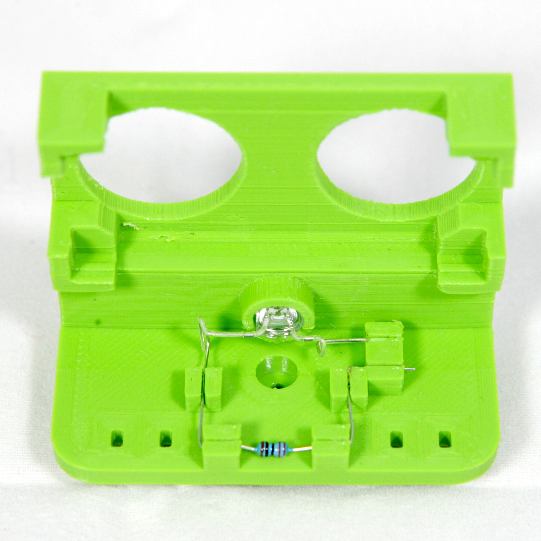
Solder the kathode of the led to the resistor lead and the blue 80mm wire to the anode.
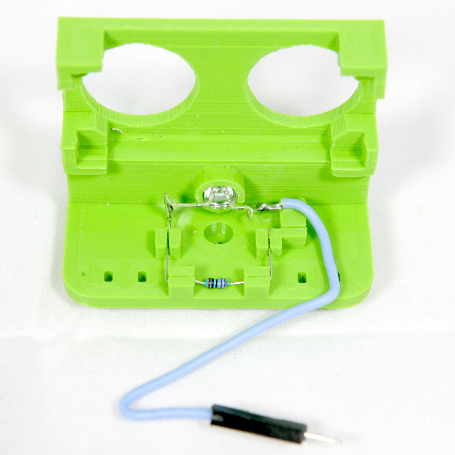
Take the HC-SR04 loom and solder the black lead without the dupont connector to the other lead of the resistor.
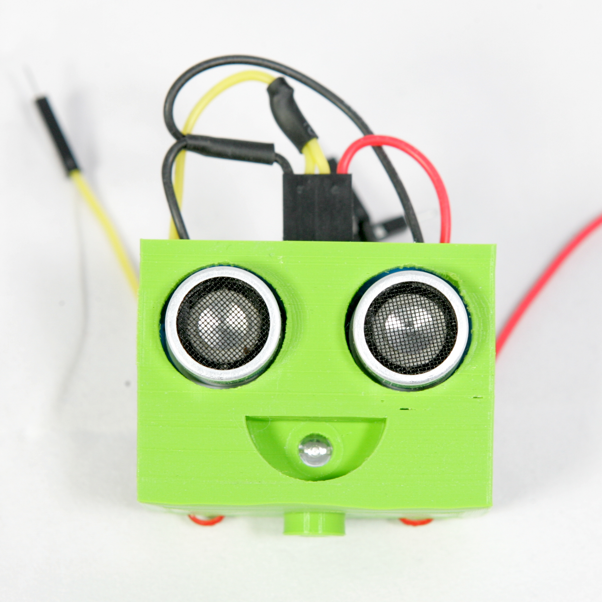
Push the HC-SR03 ultrasonic sensor gently into the socket until it clicks
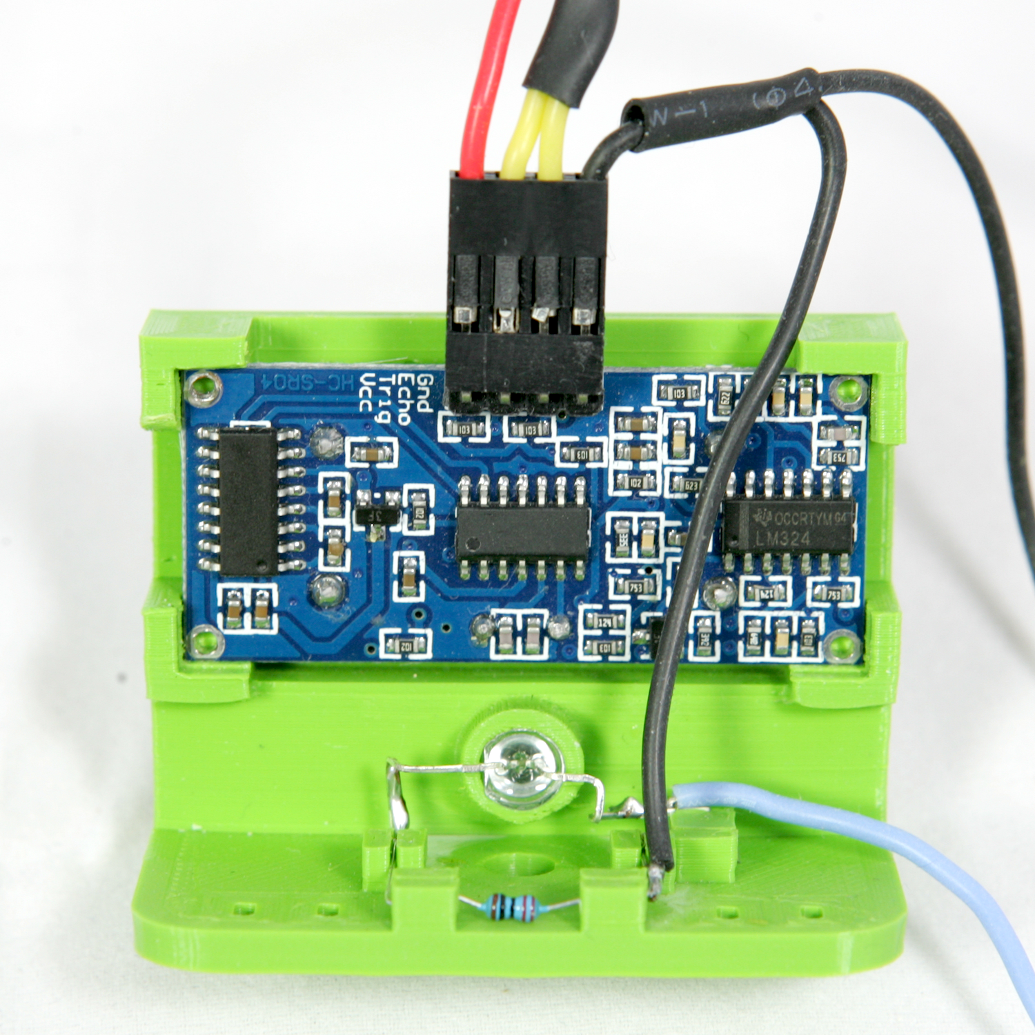
Fasten the black and red wire on the left by threading a cable-ties through an eyelet and fastening it. Repeat the process for the other side for the blue and yellow wire.
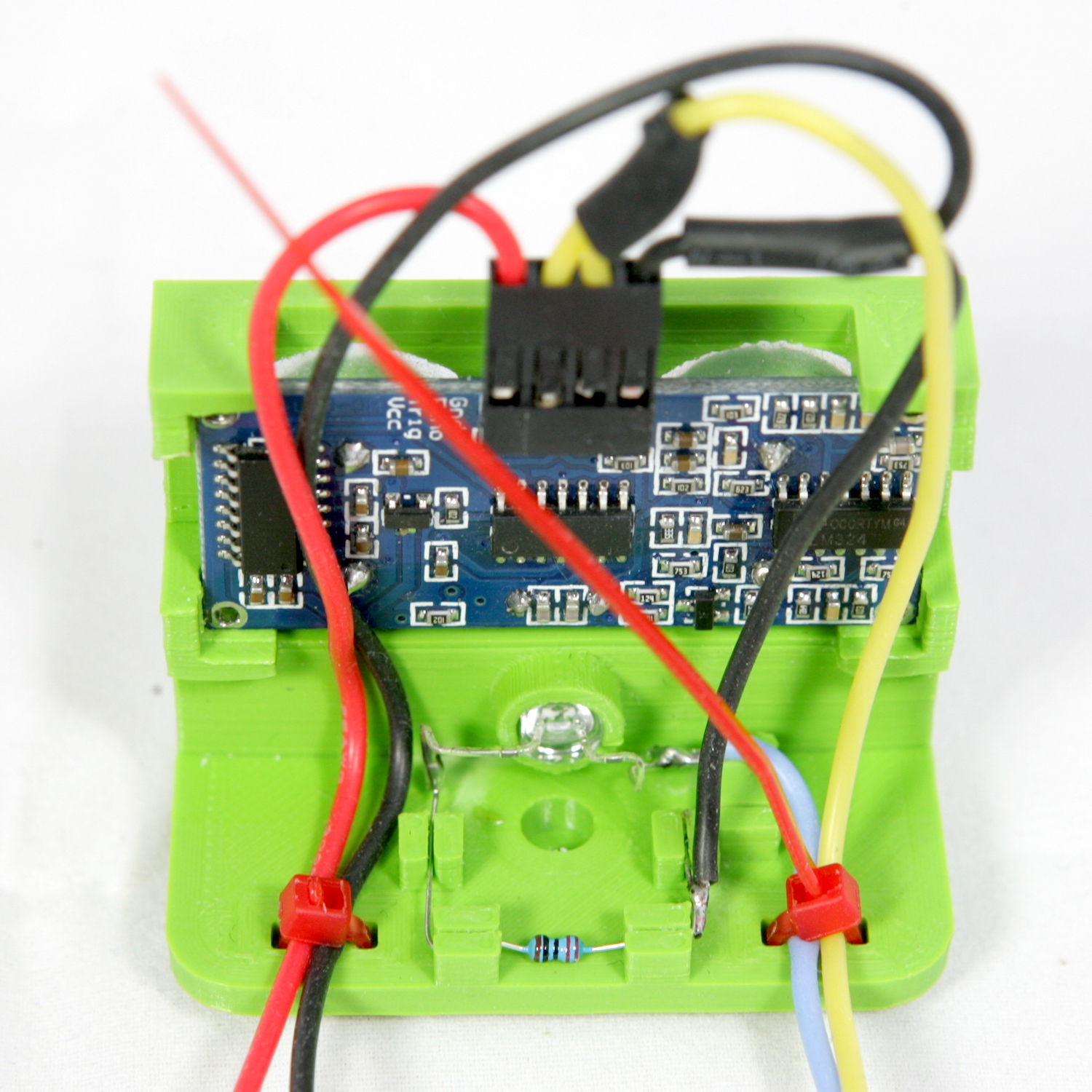
Cut of the leads of the cable-ties and the assembly of the head is finished.
The IR Sensor module has an IR light emitter and receiver. Depending on the print material and colour of the frame it may more or less conduct the IR light shine through. When conducting to much light the sensor will not able detect lines. Therefore a piece of 6mm black heat shrink tube has to be put on the IT light emitter.
Slide the heat shrink tube ove rthe IR light emitter. The emitter led is the translucent led.
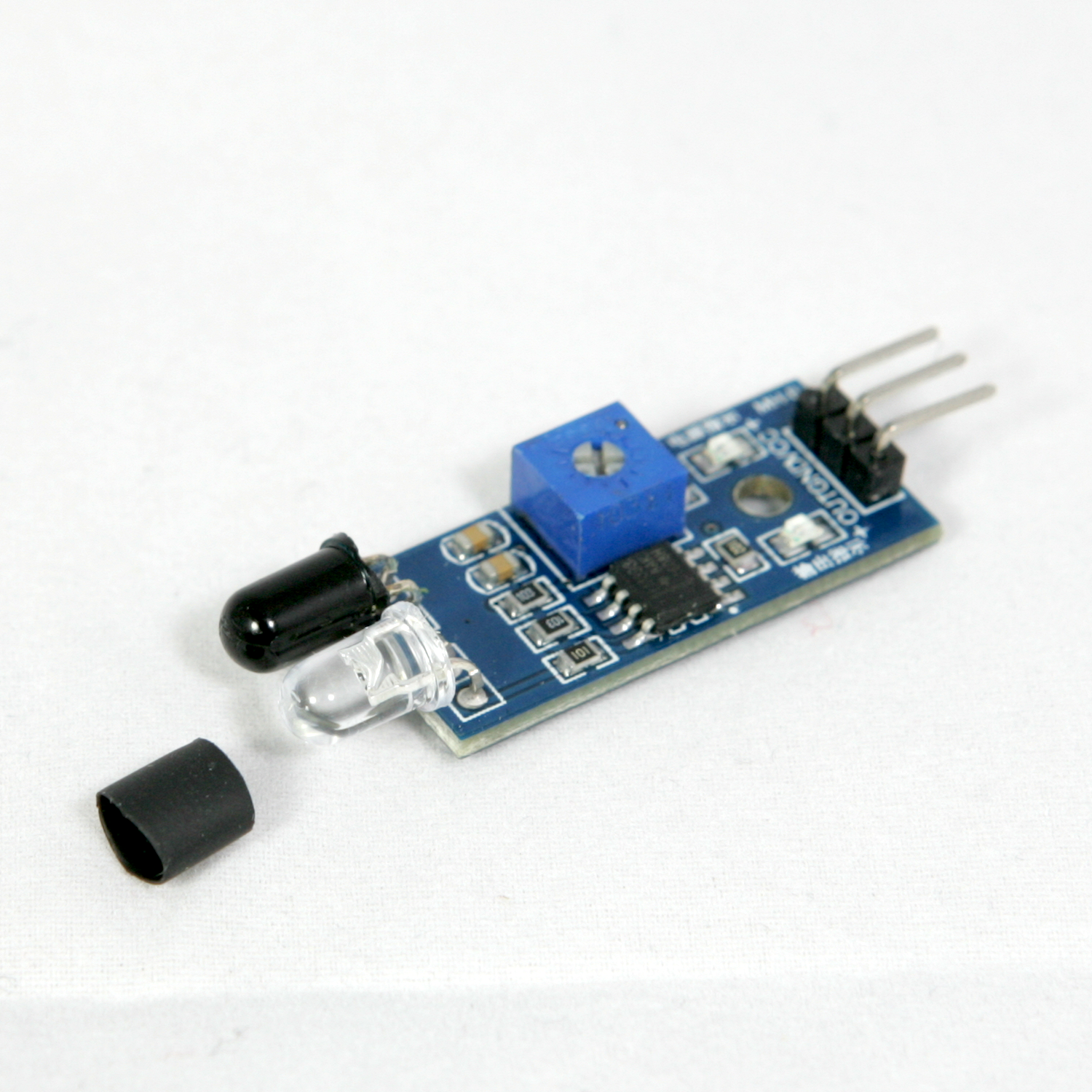
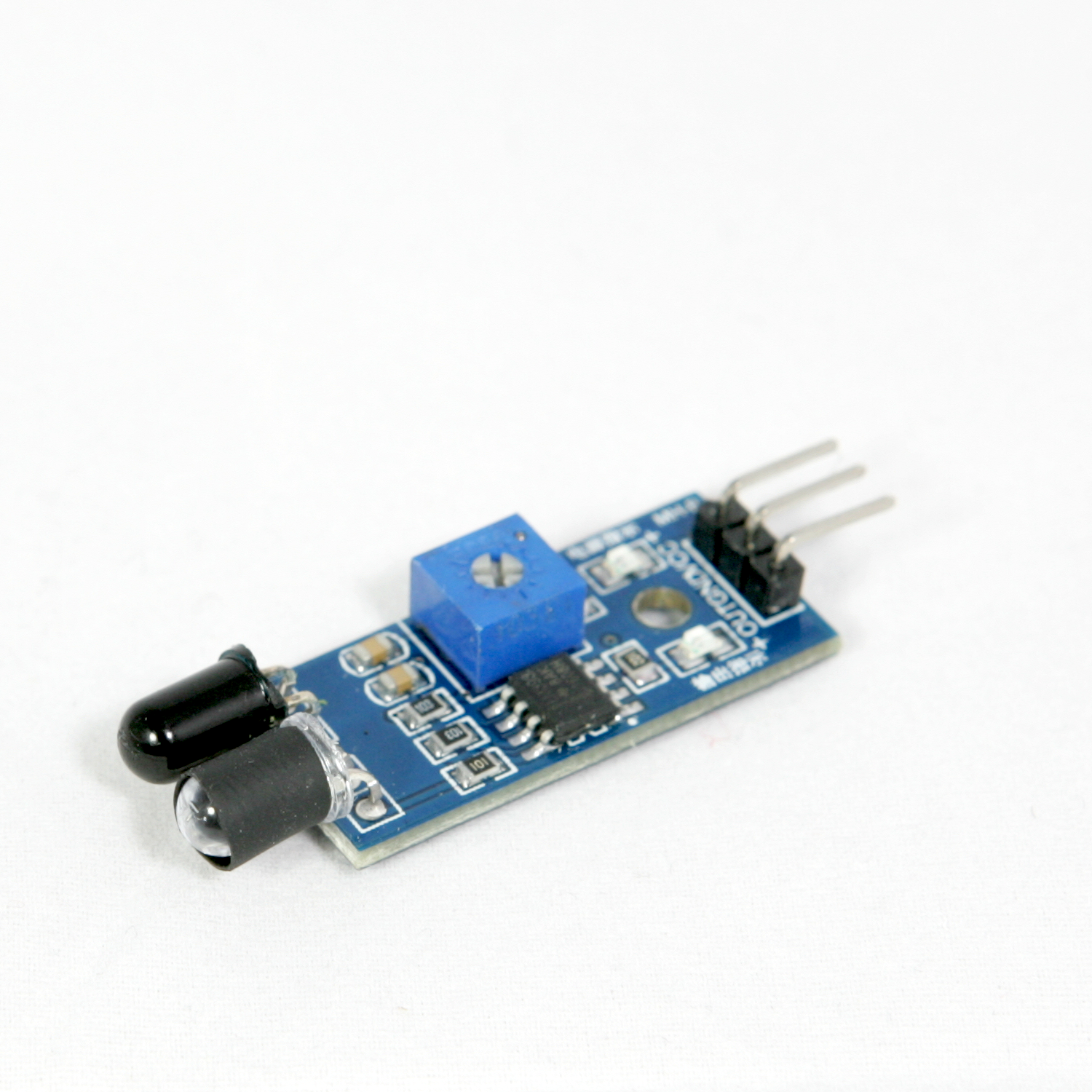
Carefully head the shrink tube, making sure the other compontents do not get overheated. The heat shrink tube must be tight enough so you cannot slide it of the led after it has been cooled down
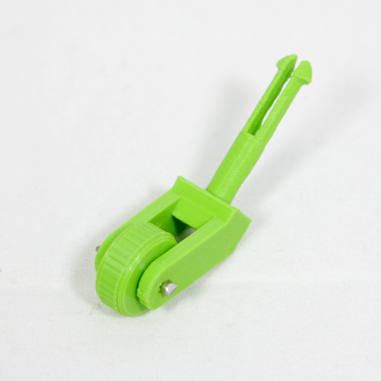
To assemble the tail wheel, cut a piece of 12mm from the 2mm Stainless Steel Round Rod.
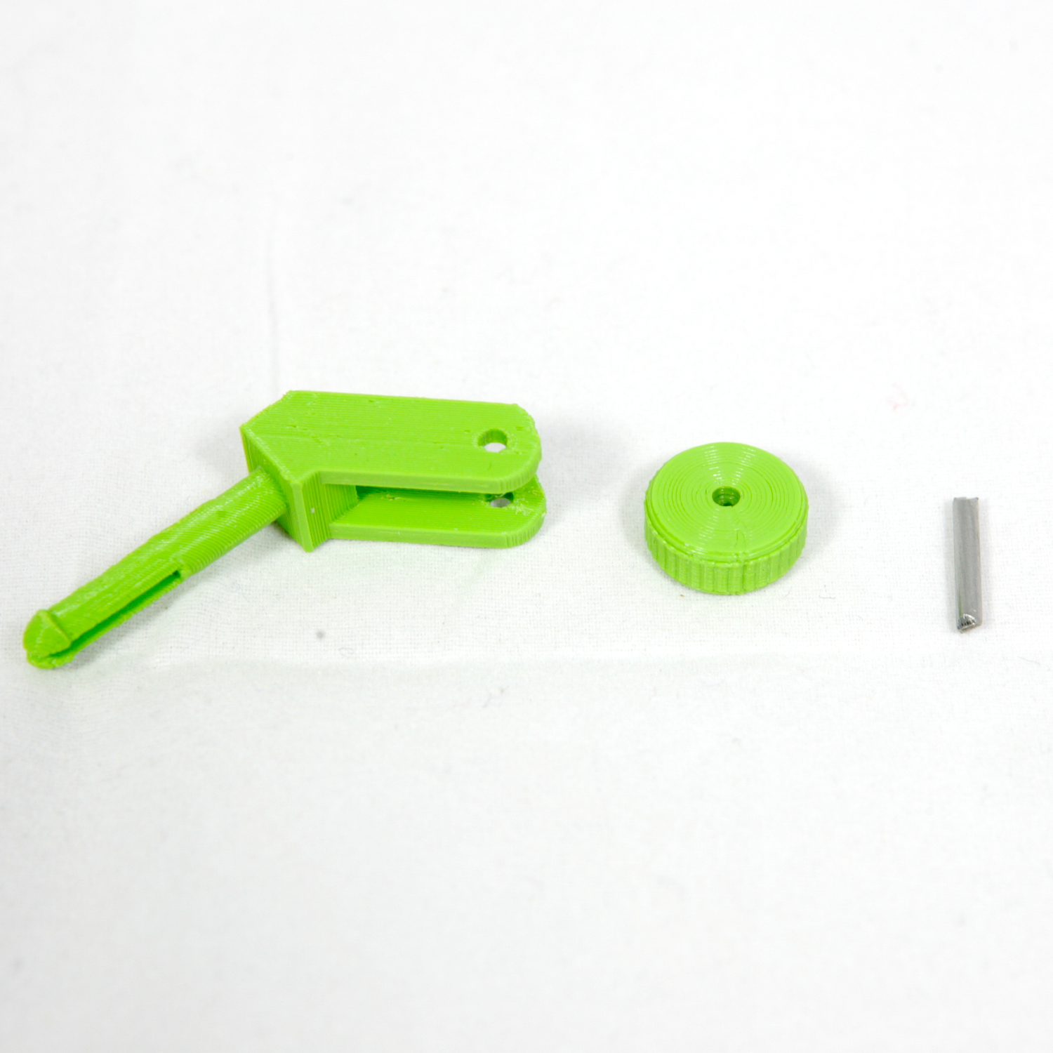
Place the wheel in the boom so the axle of the wheel is aligned with the holes in the boom. Push the rod through a hole in one side of the boom.
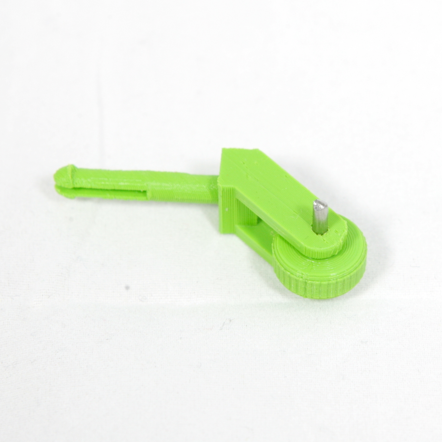
Gently push the rod untill it comes out of the hole on the other side of the boom.
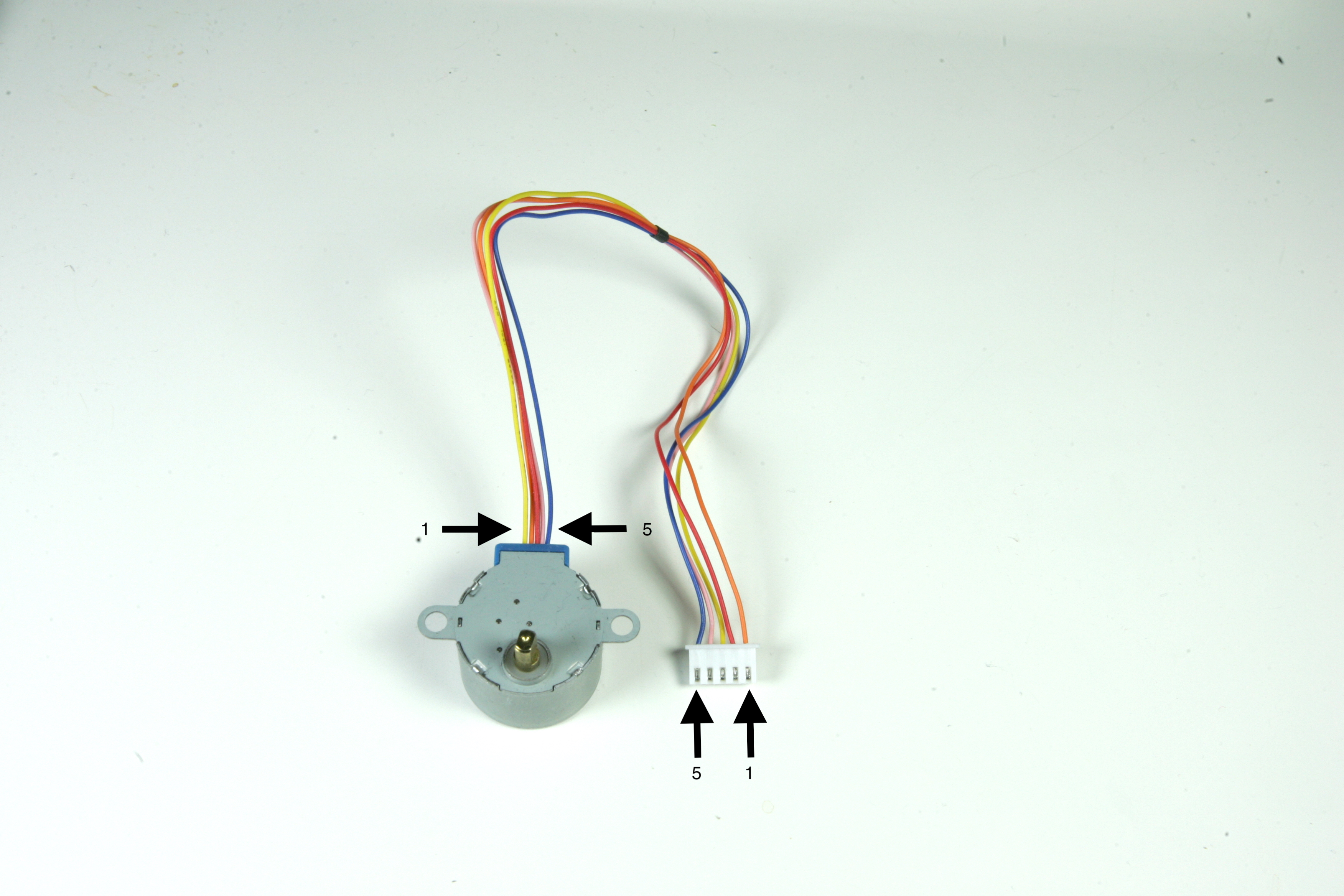
Due to a aberrant connector layout on the ULN2003 stepper motor driver boards the wiring on the stepper motor drivers have to be adapted to match the correct pins on the ULN2003.
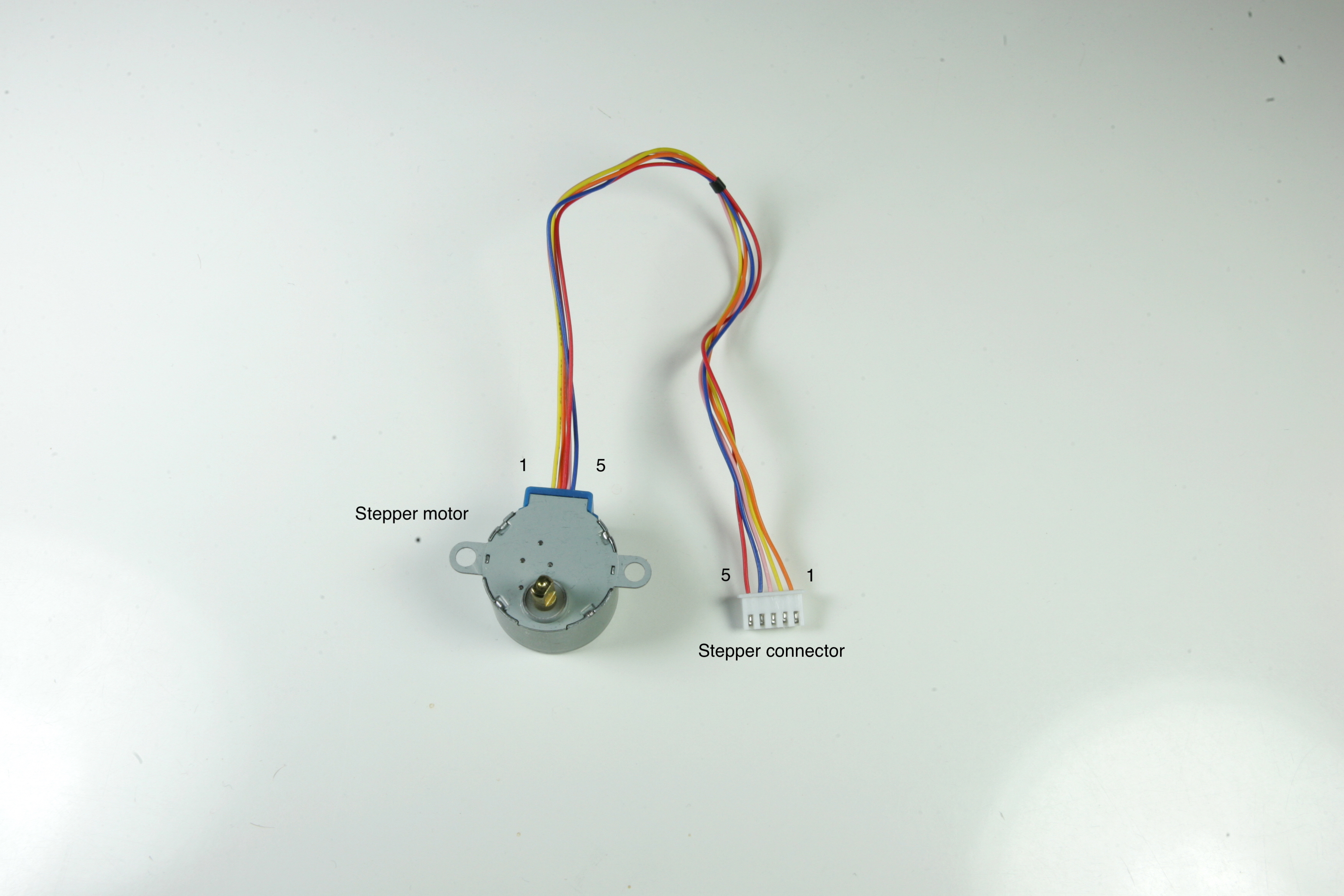
All stepper motors i have received have the following wiring configuration. With the stepper motor axis and connector side with the 2 notches facing towards you the pins are labeled 1 to 5 when counting from left to right.
On the image below the wires for a new received stepper motor are wired as follows.
stepper 1 (coil 1) to connector 3
stepper 2 (coil 3) to connector 1
stepper 3 (+5v) to connector 2
stepper 4 (coil 4) to connector 4
stepper 5 (coil 2) to connector 5
Note that the connector on the photo below is turned.
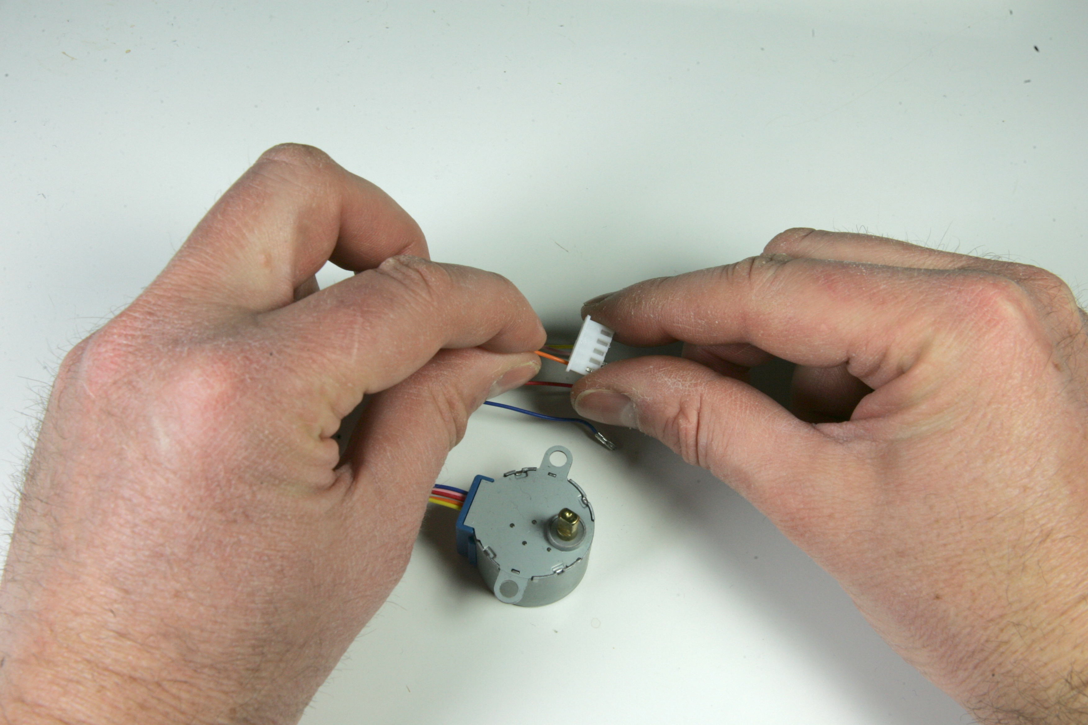
To rewire the connector, remove the wires from the connector first. I have tried different tools to removed the pins from the connector and got the best results using a T3 screwdriver bit.
Place the connector on a flat surface with the five cutouts facing upwards. Gently push the little notch, which keeps the connector in place, down,
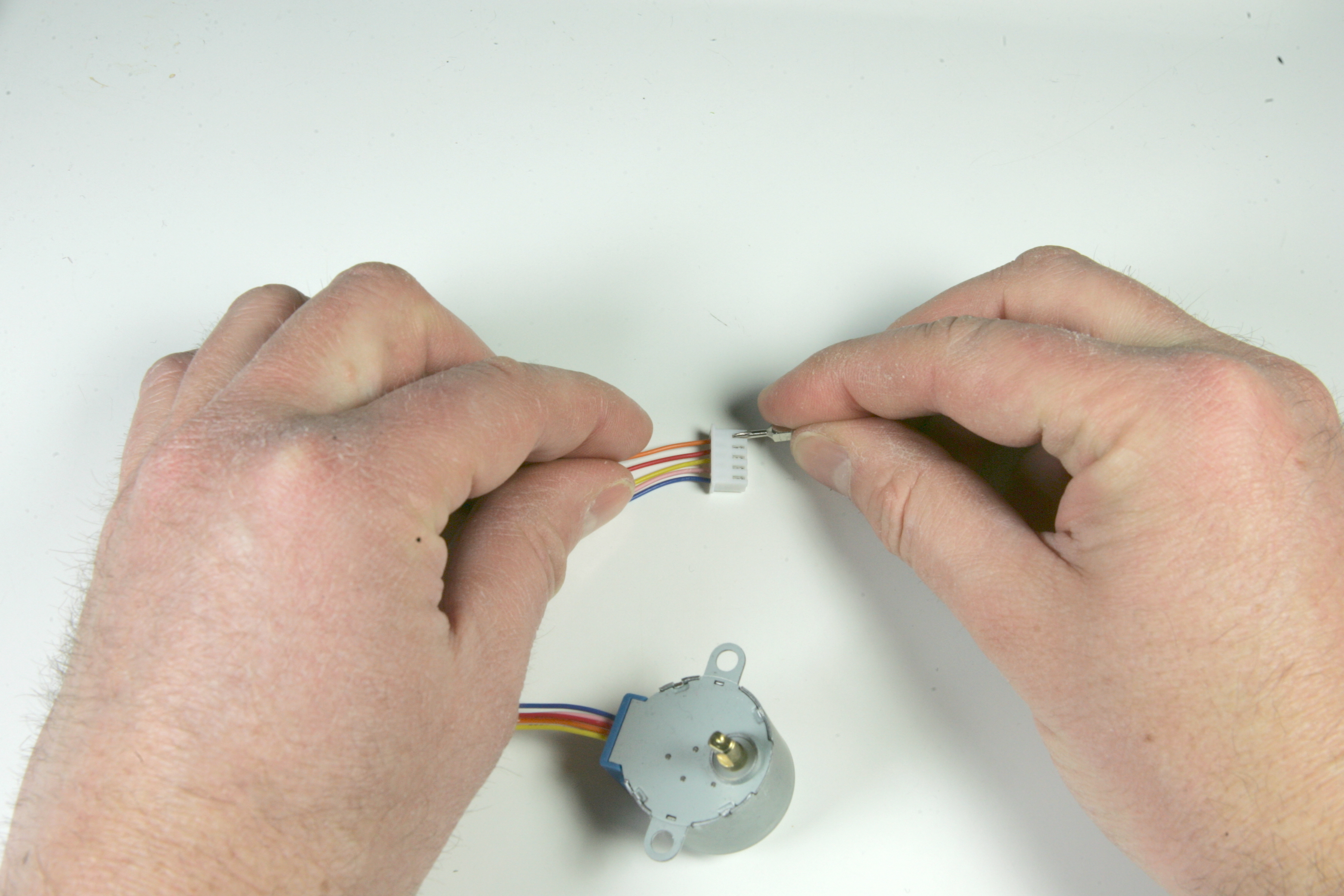
and pull the cable outside the connector at the same time.
Repeat this step for all wires.
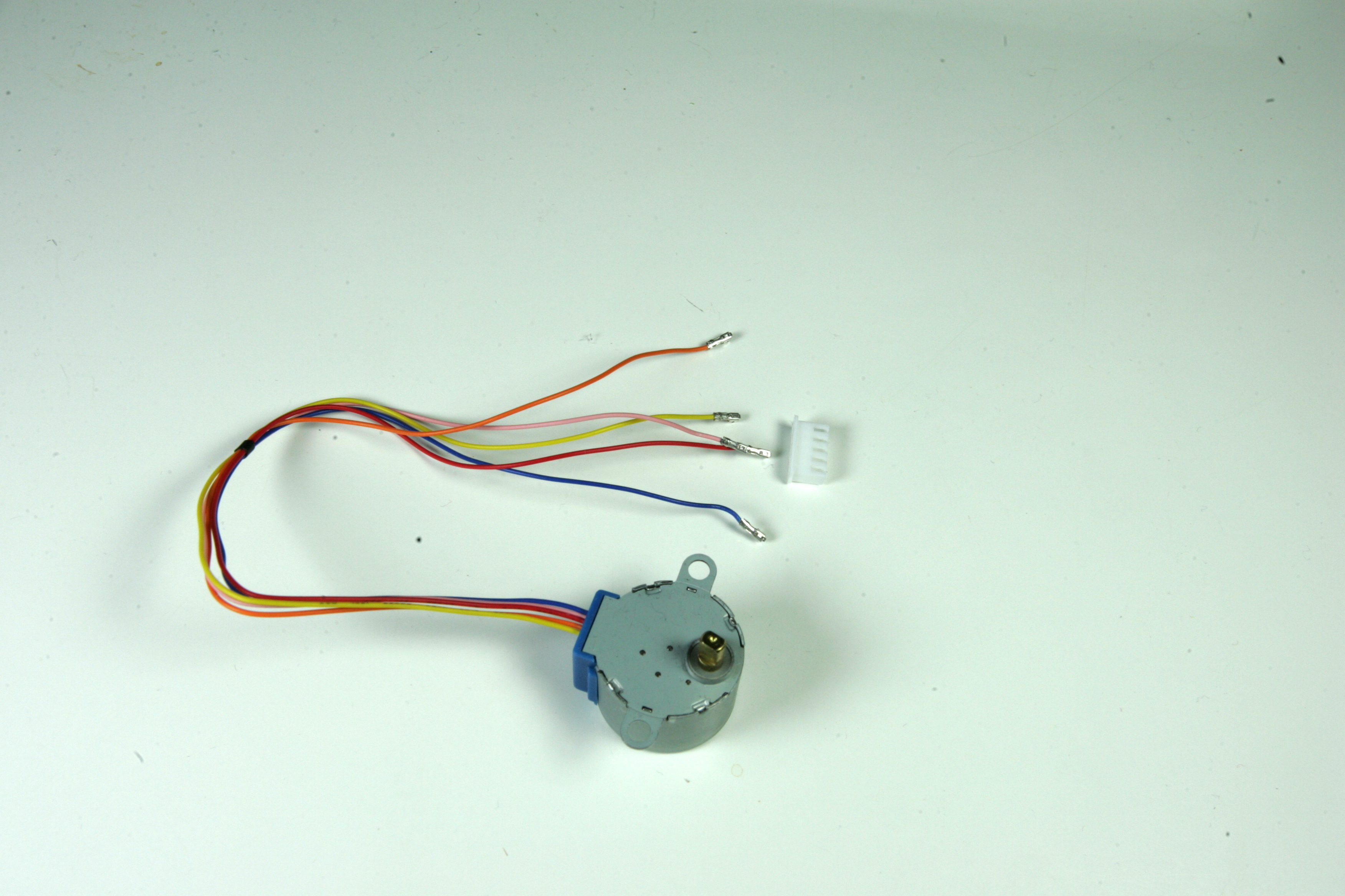
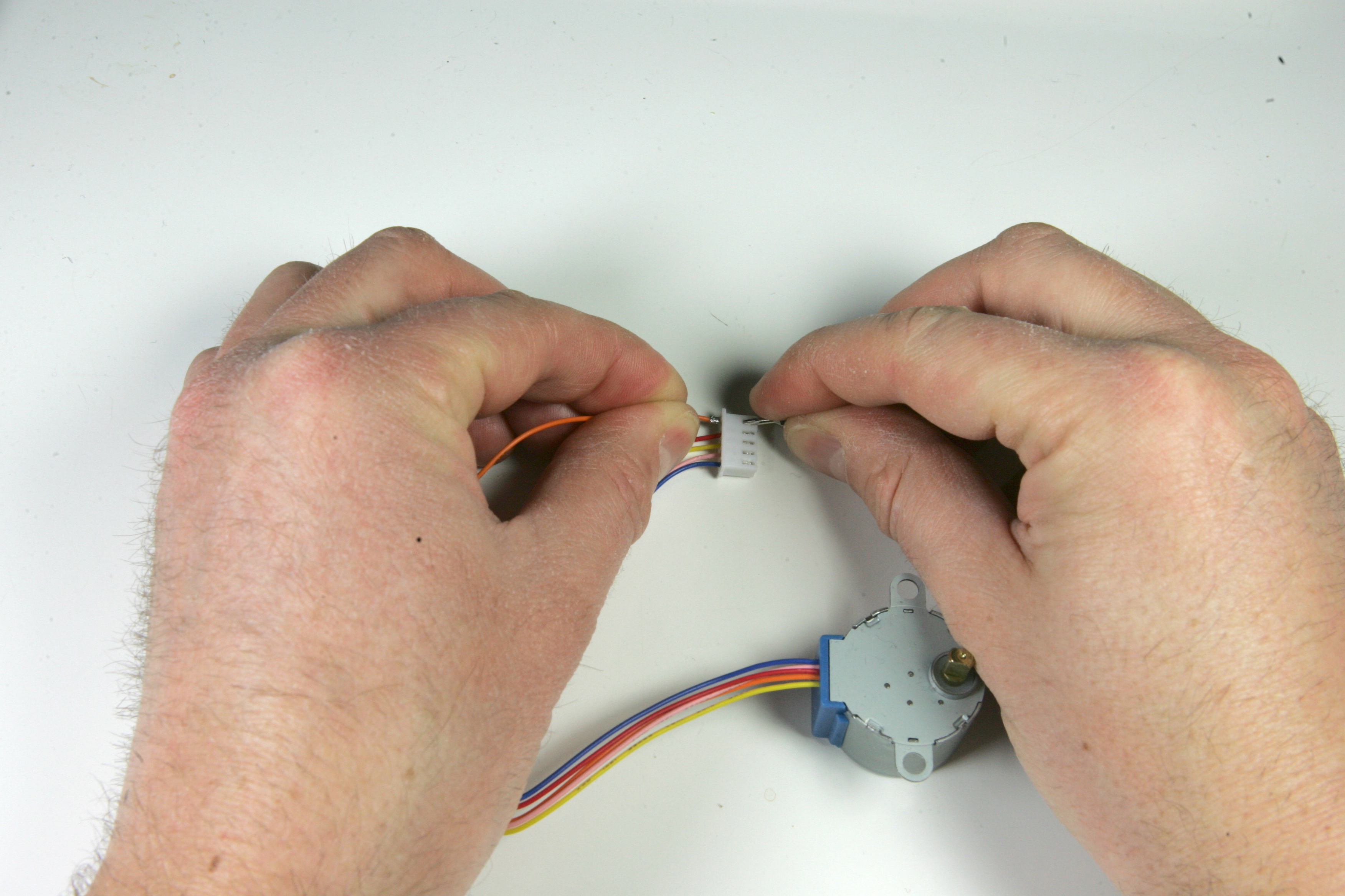
Now place the wires into the connector again, one by one.
stepper 1 (coil 1) to connector 2
stepper 2 (coil 3) to connector 1
stepper 3 (+5v) to connector 5
stepper 4 (coil 4) to connector 3
stepper 5 (coil 2) to connector 4
(Yes! the wire on the picture below is not positioned correctly 😃)
And after completion the wiring should match the image below. Ignore the colour of the wires when comparing your stepper motor wiring with the photo below. Different stepper motor suppliers do use different wire colours and ordering of colours. Only compare the order of the wires from the stepper motor.
When using Arduino Create and Chromebooks an Arduino Create subscription is required. There are two plans available for Arduino Create, a personal plan and an educational plan.
When you want to subscribe yourself to Arduino Create, visit the Chrome web store and take a monthly subscription on Arduino Create here
If you are in an educational environment, you should use the Arduino Create App for Education. A detailed description how to subscribe to subscribe to the Arduino Chrome App for Education can be found here.
Follow the instructions to create a team and add the students to the plan. If the students have been added successfully, the Arduino Create for Education Chrome app can be installed by following the steps in the Install Arduino Create for Education Chrome app article.